Introduction: From Design for Manufacture to Design for End-of-Life

For three decades, plastic enclosure design in consumer electronics optimized for a single event, besides reducing costs (and quality in certain markets): final assembly on the line. Ultrasonic welds, structural adhesives, heat-staked bosses and mixed-material overmolds all exist because they make that one event fast, cheap and mechanically reliable. None of them were built with a second event in mind — the day someone needs to open the product again to replace a battery, swap a cracked screen, or separate the materials for recycling. That second event was, for most of the industry’s history, not a design requirement at all; it was an accident of whatever the assembly process left behind.
At end of life, recyclers depend on resin marking, and a plastic identification chart helps technicians recognize unmarked enclosure plastics such as ABS or polycarbonate. A plastic identification test can then confirm the grade before the part is reused or recycled.
That has changed. The European Union is moving reparability and recyclability from a marketing claim to a legal specification, and the shift is working its way back through the design chain into the enclosure itself: which fasteners are chosen, which resins are specified, and in what sequence a technician — or an untrained consumer — is expected to get inside the product.
This article treats design for disassembly (DfD) as what it now is: a primary constraint on plastic part design, on par with structural performance, cosmetic finish and cost per unit, not a downstream problem handed to whoever writes the service manual after the product ships.
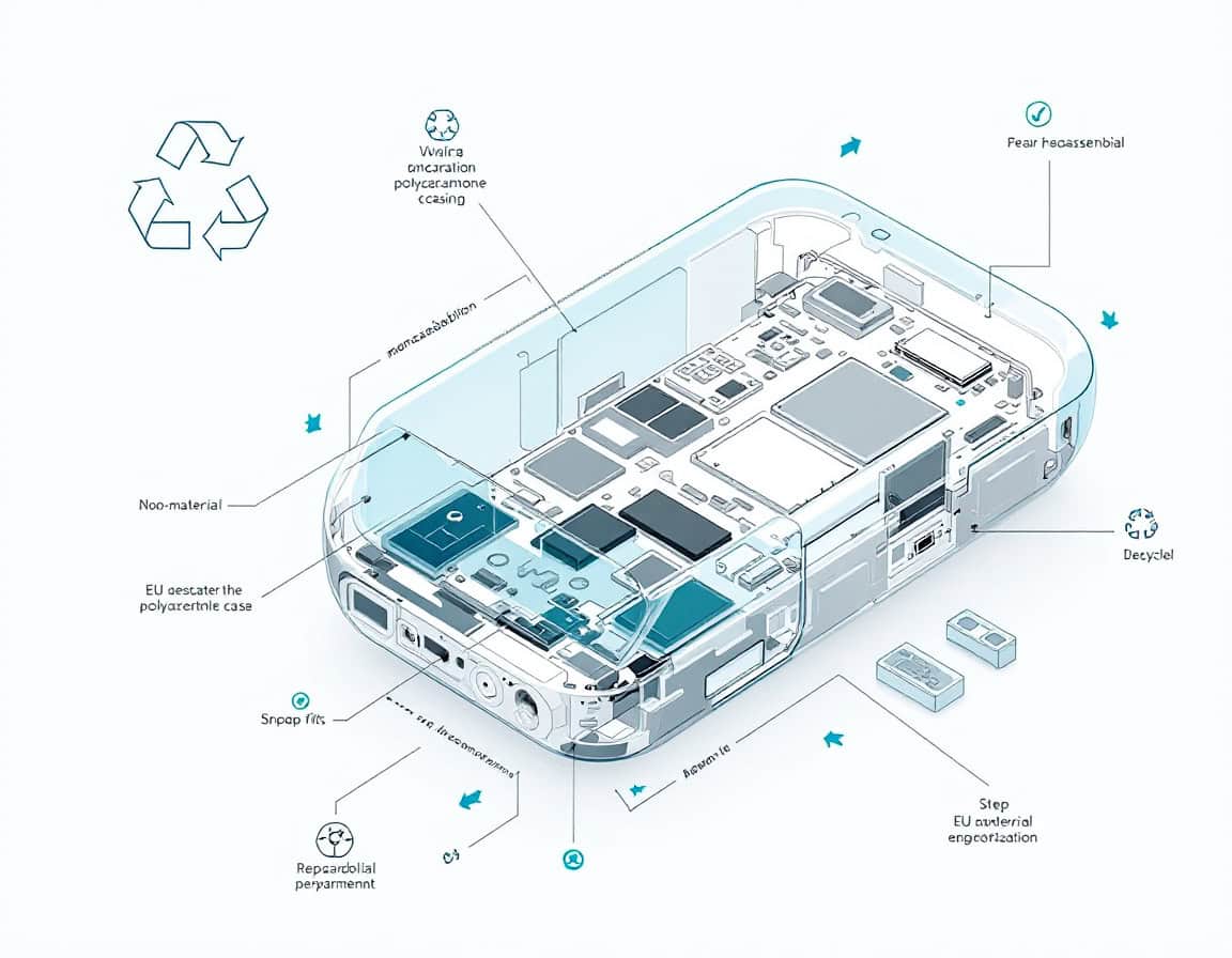
Three architectural decisions do most of the work in making a plastic enclosure disassembly-capable: how parts are joined (snap-fit versus welded or glued), how many distinct material families are present in the housing (mono-material versus mixed), and whether adhesives appear in the primary structure at all. A fourth decision, often skipped, determines whether the first three actually pay off in practice: whether the disassembly sequence is legible to someone who has never seen the product opened before. This article works through the regulatory drivers, the three architectural pillars in engineering depth, the human-factors layer that makes the design usable, and the validation and business case that close the loop.
Disclaimer: as of 2026, specifically for a few regulatory specifics (ESPR delegated-act timing, exact spare-parts-window ranges, the 25g marking threshold) are stated as general industry practice rather than pinned to a specific clause, since delegated acts under ESPR are still being finalized category by category — worth a compliance-team pass, or a regulation check and update before taking all of what’s below as granted.
Very complementary to this article, to get as much technical alternatives as possible, we also recommend the ready of:

The Regulatory Forces Making Disassembly Mandatory
Four EU instruments now act directly on enclosure design, and each pulls on a different part of the product lifecycle. Treating them as one undifferentiated “sustainability requirement” leads to designs that satisfy the letter of one instrument while missing another. It is worth separating them precisely, because each implies different engineering constraints:
| Instrument | What it governs | Design implication |
| Ecodesign for Sustainable Products Regulation (ESPR), in force since July 2024 | Framework regulation empowering the Commission to set product-specific durability, reparability, recyclability and Digital Product Passport requirements via delegated acts | Enclosures must anticipate quantified disassembly-depth and disassembly-time limits once product-category delegated acts land; designs frozen against a moving regulatory target age badly |
| Right to Repair Directive (EU) 2024/1799 | Obliges manufacturers of specified product categories to offer repair beyond the legal warranty, at reasonable cost, using original or compatible parts | Spare parts must be physically removable without destroying adjacent components; repair cannot be economically viable if it requires shell replacement to reach one failed part |
| WEEE Directive 2012/19/EU | Producer responsibility for collection and recycling of electronic waste, with material-recovery targets | Housings must separate into recyclable material streams within the time and equipment constraints of commercial recycling facilities, not idealized lab conditions |
| Battery Regulation (EU) 2023/1542 | Requires portable batteries in appliances to be removable and replaceable by the end user, with staged compliance dates extending toward 2027 for many categories | Battery compartments cannot be behind adhesive-sealed shells or heat-staked closures; the removal path must not require destructive tools |

The engineering standard that operationalizes several of these, EN 45554, defines the actual assessment methods regulators and test labs use: general methods for evaluating the ability to repair, reuse and upgrade energy-related products, including timed disassembly protocols and fastener-accessibility scoring. Designers who benchmark against EN 45554 directly, rather than against a general sense of “should be repairable,” get a design that survives conformity assessment on the first pass.
Two implications matter more than the letter of any single directive:
- These instruments are converging, not staying siloed — a battery compartment now has to satisfy Battery Regulation removability and ESPR disassembly-depth logic simultaneously, on the same joint.
- The delegated acts under ESPR are still being written category by category, which means enclosures designed today should be engineered with margin against tightening thresholds, not against today’s minimum.
Tip: build a compliance traceability matrix at the component level as soon as the industrial design freezes — one row per fastener or joint, columns for which of the four instruments touch it. Retrofitting this matrix after tooling is cut is far more expensive than generating it during the DfM review, and it is exactly the artifact a notified body will ask for during conformity assessment.
Design-for-Disassembly Fundamentals: Vocabulary and Metrics

Before addressing joints and materials, it helps to fix the vocabulary this article uses, because these terms carry precise engineering meaning in the DfD literature and in EN 45554 itself.
- Disassembly depth is the number of parts or joints that must be removed, in sequence, before a target component is accessible. A battery reachable after removing one back cover has a depth of one; a battery buried under a mainboard, a shield can and an adhesive-bonded midframe has a depth of four, even if every individual joint is technically reversible.
- Disassembly sequence is the order those removals must happen in. A well-designed product has a sequence with few dead ends — removing part A never requires first removing and then reinstalling part B to get a tool in at the right angle.
- Tool dependency classifies each joint by what is needed to open it: tool-free (finger-operable snap or latch), standard tool (a screwdriver bit found in a typical household or basic repair kit), or special tool (proprietary bits, adhesive-cutting wire, heat guns). Right to Repair compliance effectively eliminates the special-tool category from any joint that sits on the path to a mandated spare part.
- Destructive versus non-destructive disassembly distinguishes joints that survive opening (screws, most snap-fits, connectors) from those that do not (heat-staked bosses, solvent-bonded seams, most adhesive layers). A recycling stream can tolerate, or even prefer for some kinds of, destructive separation at end of life; a repair path cannot, because the part being removed usually needs to go back in.
These four measures compose into the DfD hierarchy that governs every decision in the chapters that follow: reduce the number of joints first, make the remaining joints reversible second, and make reversible joints physically and cognitively accessible third. Each pillar in this article maps to one rung of that hierarchy — mono-material design attacks joint count indirectly by removing the need for material-transition fasteners, snap-fit architecture makes joints reversible, and the intuitive-disassembly chapter makes them accessible.
Tip: score disassembly depth and tool dependency for every subassembly during the concept phase, before surfaces are styled. It is a five-minute exercise on a bill of materials and it catches architecture problems — a battery buried under the antenna module, for instance — that are nearly free to fix on paper and extremely expensive to fix after tooling.
Pillar One: Snap-Fit Architecture as a Disassembly-Native Joint
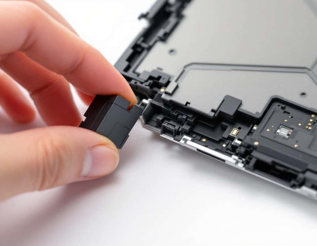
Snap-fits are the only joining method in this article that was not repurposed for disassembly — they were, in their original patent literature from the 1940s onward, conceived as reversible. Making them serve as the primary structural joint in a repairable, mono-material enclosure requires engineering them for a duty cycle they were rarely designed for in high-volume consumer electronics: dozens of open-close cycles performed by someone without assembly-line training, using inconsistent force and angle.
Geometry and joint types
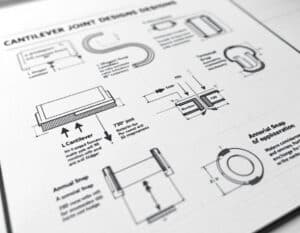
Three cantilever families cover almost all enclosure applications:
- The straight cantilever hook is the simplest: a beam with a hook at the tip, deflecting on insertion and springing back to lock. Its retention force is set by hook engagement depth and undercut angle; its release force by the same undercut angle from the opposite direction, plus whatever access the design gives a release tool.
- The L-shaped or U-shaped cantilever trades some stiffness for a longer effective beam length in a smaller footprint, useful where wall space is constrained but deflection needs to stay within the elastic strain limit of the resin.
- The torsional snap (sometimes called a cantilever hinge or flexure latch) loads the beam in torsion rather than bending, giving a more compact packaging envelope at the cost of higher local stress concentration at the torsion axis — a detail that matters directly for fatigue life, addressed below.
Annular (circular) snaps, common on caps and battery covers, distribute the deflection around a full ring rather than a single cantilever, which lowers peak strain per unit of retention force but requires more uniform wall thickness around the circumference to avoid one segment taking a disproportionate share of the load.
Tip: as suggested at the end of the intro above, we strongly suggest to refer to our > Plastics Design Tricks Collection <.
Sizing for repeated, non-professional cycling
The insertion-force-versus-retention-force asymmetry is the core design lever. Insertion force is governed by the entry angle (typically 30–45°) and can be kept low without compromising the joint. Retention force is governed by the return angle, which in an assembly-only snap can be steep — 90°, an undercut with no deliberate release path — because the assumption is the joint is never meant to open again outside of destructive service. A disassembly-native snap instead uses a moderate return angle (typically 30–45°, sometimes matched to the entry angle for symmetric behavior) combined with a defined release feature: a finger-accessible tab, a screwdriver-slot lever point, or a ramped release surface reachable by a flat tool without marring adjacent cosmetic surfaces.
Strain must stay comfortably below the resin’s allowable strain limit for repeated cycling, not just its one-time yield strain. For unfilled polycarbonate, a single-cycle allowable strain around 6% is common design guidance, but a joint expected to survive 20–50 repair-driven cycles over a product’s service life should be designed to a working strain closer to 2–3%, with the difference absorbed by a longer or thicker beam rather than a tighter, more strained geometry. Glass-filled resins tolerate far less strain before fiber-matrix debonding — typically 0.5–1% — which is why structural snap-fits on repair-critical joints are usually specified in unfilled or lightly filled grades even when the rest of the housing uses reinforced material for stiffness.
Important for design: this does not account for the inherent ageing weaknesses of plastics: heat, UV, chemicals … depending on application and usages, may age the resin way faster that the direct usage strain. Furthermore, it would be a shame to improve the disassembly element if this is this element that is the cause of the failure!
Failure modes specific to repair-cycle use
Note: TBD if a product submitted to frequent repair-cycles is a good thing … (at least that supposes it is repairable).
Three failure modes appear specifically because these joints are opened by end users repeatedly rather than assembled once on a line:
- stress whitening at the hook root from repeated flexure,
- progressive rounding of the hook profile from off-axis release-tool contact,
- creep relaxation of retention force when the joint sits under sustained deflection between cycles (relevant mainly for interference-fit designs rather than snap-fits proper, but common in hybrid joints).
Root radii of at least 0.5× wall thickness at the base of every cantilever beam address the first two failure modes directly by moving peak stress away from the surface a release tool contacts. A generous, consistent root radius also reduces sink marks on the opposite cosmetic surface, aligning the disassembly requirement with a molding-quality requirement rather than trading against it.
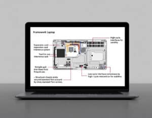
Example: the Framework laptop’s mainboard and expansion-card retention is a useful reference point: expansion cards use a straight-pull, tool-free interference latch rather than a screw, sized specifically for hundreds of insert/remove cycles by a non-technical user, while structural chassis joints that see less frequent access use standard Torx screws rather than snaps — an explicit design decision to reserve snap-fit for genuinely high-cycle interfaces and use captive fasteners where cycle count is low but torque retention matters more.
Tip: run a Weibull-based cycle-fatigue test on the actual molded part, not a CAD-simulated beam, before freezing hook geometry. Injection-molded fiber orientation and weld lines near the beam root shift the real fatigue curve enough from the simulation that a design validated only in FEA regularly under-performs its predicted cycle life by 30–50%.
Pillar Two: Mono-Material Housings
A joint can be perfectly reversible and the enclosure can still fail a recycling audit, because reversibility solves the repair problem but not the material-separation problem. A shell molded in ABS, joined without adhesive to a PC/ABS blend bezel, with a glass-filled nylon internal bracket and a die-cast aluminum shield can bonded in with double-sided tape, is fully “disassemblable” by the strict definition and almost worthless to a mechanical recycler, because none of those material streams can be commingled without degrading the regrind’s mechanical properties below usable specification.
What consolidation actually meansMono-material design does not mean literally one resin in the product — PCB substrates, wiring, batteries and optics remain distinct. It means consolidating the structural housing, chassis and cosmetic surfaces that together make up the bulk plastic mass into one resin family, so that when the housing is separated from electronics at end of life, the largest mass fraction goes into a single, high-value recycling stream instead of fragmenting into several low-value ones. In practice this usually means selecting one base polymer — PC, ABS, PC/ABS blend, or a PP grade for lower-stress applications — and using geometry, not material substitution, to hit the different mechanical requirements different zones of the housing carry. | Resin identification and sortabilityISO 11469 marking (the resin identification code molded or printed directly onto each part) is necessary but not sufficient. Automated optical or near-infrared sorters at recycling facilities can read polymer type from the material itself, not from an embossed code that may be on an internal, non-visible face; the marking matters for manual disassembly audits and for the technician deciding whether two parts can go in the same bin, but it does not substitute for actually using compatible resins across the assembly. A mono-material housing marked correctly and consistently is auditable by both machine sorting and manual disassembly; a mixed-material housing with perfect marking is still a mixed-material housing. |
See also for that our complete guide:

and also:

Compensating for lost material-mix flexibility
Mixed-material design exists in the first place because different housing zones carry different loads: a hinge boss needs toughness and fatigue resistance, a battery-adjacent wall needs flame retardancy, an external cosmetic surface needs scratch resistance and color stability, and a shielding zone historically needed a conductive material. Losing the ability to swap resin by zone pushes the engineering burden onto geometry and additive packages within a single base resin family.
- Local stiffness is tuned with rib density and wall-thickness transitions rather than switching to a glass-filled grade in one zone only — keeping fiber content uniform across the shot avoids a secondary recycling incompatibility (short-fiber-filled and unfilled grades of the same base polymer are usually blend-compatible in regrind; wildly different filler loadings across zones are not, once ground and mixed).
- Flame retardancy is now available in non-halogenated, recycling-compatible additive packages for PC and PC/ABS that do not require switching to a distinct resin family purely for a battery-adjacent zone.
- EMI shielding, traditionally solved with a bonded metal can or a sprayed conductive coating (both recycling contaminants), is increasingly handled with conductive-filled plastic zones molded in the same base resin, or with a mechanically clipped — not bonded — shield that separates cleanly at disassembly and is recycled as a distinct metal stream rather than a contaminated plastic one.
- Cosmetic finish differences (soft-touch versus gloss) are achieved with surface texture (VDI/SPI mold finish) and in-mold or applied coatings compatible with the base resin’s recycling stream, rather than a bonded second material.

Good application to follow: Fairphone’s chassis strategy is the clearest public illustration of this trade-off resolved in production: a housing built predominantly around a small number of compatible resin families, mechanically fastened rather than bonded, explicitly documented down to material composition per part in service literature — at a measurable cost in industrial design flexibility (visible parting lines, screw heads, a thicker chassis) that the product accepts deliberately in exchange for a Right-to-Repair and recyclability profile competitors using bonded multi-material shells cannot match without a redesign.
Tip: run a regrind compatibility matrix before finalizing resin selection — not just “is material X recyclable,” but “can material X’s regrind be blended back into virgin X at the required letdown ratio without falling out of mechanical spec.” Suppliers publish this data for their grades; cross-referencing it against every resin actually specified in the BOM, including secondary suppliers used for the same nominal grade, catches incompatibilities that a single-supplier material data sheet review misses.
Pillar Three: Eliminating Adhesives — Mechanical and Thermal Joining Alternatives
Adhesives and solvent bonds are attractive (*see design note below) in assembly because they seal, they dampen vibration, they hide tolerance stack-up, and they require no fastener bill of materials. Every one of those advantages becomes a liability at disassembly: a cured structural adhesive does not release without heat, solvent or force sufficient to damage the substrate, and the bond line itself contaminates whichever material stream captures the larger piece of the joint.
Design note: … but validation is hard, ageing prediction is risky, and can be time-consumming in the manufacturing process.
Mechanical fastening as the defaultCaptive screws — screws that stay retained in the part they pass through even when backed out, via a shoulder or a molded boss with a compliant collar — solve the single biggest practical repair failure mode: lost fasteners during reassembly. Standardizing on a single screw head type and drive size across as much of the product as possible (Torx or Phillips, one or two lengths) is a disassembly-time reduction with essentially zero part cost, and it is exactly the kind of detail EN 45554’s tool-count scoring rewards directly. Elastomeric gaskets, compressed by the same screws that hold the housing together, replace the sealing function adhesives previously provided, at the cost of requiring a defined compression groove and consistent clamp load across the perimeter — a tolerance-stack problem adhesives papered over by filling any gap. This is a real engineering cost, not a free substitution, and it needs to be budgeted into the tolerance chain from early in the mechanical design rather than patched in after the adhesive is removed late in development. | Welding methods and their disassembly compatibilityUltrasonic and laser welding both produce joints that are, by any practical definition, non-reversible: the weld line fuses the two parts’ polymer chains together, and separating them again means cutting or breaking, not unfastening. They remain useful in this framework only for joints that sit entirely outside the disassembly path — an internal, sealed sub-enclosure with no field-serviceable content inside it, for instance — and even there, using them narrows future repairability if a design assumption about “no serviceable content” turns out to be wrong two product generations later. The practical rule: if a joint is on the path to any component covered by Right to Repair spare-parts obligations or Battery Regulation removability, welding is disqualified regardless of its assembly-line advantages. |
Debonding-on-demand adhesives
Where a bonded seal is genuinely unavoidable — IP68 water ingress protection on a seam that cannot tolerate a gasket’s compression tolerances, for example — a growing category of thermally or electrically releasable adhesives offers a middle path (think twice here!). These formulations hold full bond strength through normal use and release cleanly at a defined trigger temperature (commonly in the 90–150°C range, well above use conditions but reachable with a standard heat gun or a hot plate at a repair bench) or under a low-voltage electrical pulse across a conductive layer in the bond line. They cost more per unit than a standard structural adhesive and require the joint to be designed so the release temperature does not also damage adjacent components (batteries and displays both have their own thermal limits well inside that range), but they are the only current option that lets a design keep true adhesive sealing performance while remaining non-destructively serviceable.
| Joining method | Reversibility | Sealing capability | Best use in a DfD enclosure |
|---|---|---|---|
| Snap-fit | Fully reversible, rated for cycles | Low without added gasket | Primary structural and access joints |
| Captive screw + gasket | Fully reversible | Good, with tolerance discipline | Sealed enclosures, battery covers, high-clamp-load seams |
| Ultrasonic / laser weld | Non-reversible | Excellent | Sealed sub-assemblies with no field-serviceable content, only |
| Standard structural adhesive | Non-reversible without damage | Excellent | Avoid on any Right-to-Repair or Battery Regulation path |
| Debonding-on-demand adhesive | Reversible with defined trigger | Excellent | Seams needing true adhesive sealing that must remain serviceable |
Example: Apple’s Self Service Repair program, launched in 2022, is instructive precisely because of what it had to change to exist: display and battery adhesive on iPhone shifted toward release mechanisms compatible with a specified low-voltage or controlled-heat removal procedure documented in the public repair manual, rather than a generic structural bond assumed to be destroyed on every repair. The underlying enclosure retains adhesive for its sealing performance, but the adhesive itself was re-engineered for defined, repeatable release rather than one-way application. Were these measures enough for DfD, in a easy way, cheap, and by anyone ?
Tip: when a debonding-on-demand adhesive is used, specify and document its release procedure in the same repair manual required under the Right to Repair Directive — a reversible adhesive that no external repairer knows how to release delivers none of its repairability benefit in practice.
Cross-Cutting System Trade-Offs
Each pillar above resolves its own trade-offs internally. Three additional trade-offs only appear once snap-fit joints, mono-material housings and adhesive elimination are combined in the same product, and they need to be engineered together rather than pillar by pillar.
Ingress protectionRemoving adhesive as the primary seal and replacing it with gasket-and-screw sealing changes an IP rating from a bond-line property (uniform, tolerant of minor surface irregularity) to a clamp-load property (dependent on consistent compression across every fastener location). Achieving IP67/IP68 with a gasketed, snap- or screw-assembled seam is achievable and common in outdoor and rugged-rated equipment, but it requires a continuous compression-groove design validated with clamp-load simulation across the full perimeter, not just at fastener points, plus incoming-inspection gauging on gasket compression set over the product’s service life. |  |
EMI/RFI shielding continuityA metal shield can bonded across a seam is electrically continuous by construction. A mechanically clipped, non-bonded shield — the disassembly-compatible alternative — needs a spring-finger or conductive-gasket interface at every separation point to maintain shielding effectiveness across the joint, adding parts count and requiring EMI validation at the specific clip pitch and contact-force combination chosen. This is a genuine cost of the mono-material and adhesive-free pillars interacting: the shielding solution that was simplest under the old assumptions (bond a can down, ignore joint continuity) is no longer available, and its replacement needs its own qualification pass. | Structural and drop performanceBonded and welded joints typically outperform snap-fit and screwed joints in peak impact load transfer, because the bond line distributes load continuously rather than concentrating it at discrete fastener points. Recovering drop-test performance in a snap-fit, screw-fastened, mono-material enclosure generally means adding local reinforcement — gussets, increased wall thickness near fastener bosses, or a compliant internal chassis that absorbs impact energy before it reaches the housing joints — rather than assuming joint strength alone will match a bonded baseline. This is where many first-pass DfD redesigns fail drop qualification and need a second iteration; budgeting for that iteration in the program schedule, rather than treating it as a surprise, is the practical fix. |
Tip: validate IP rating, EMI shielding and drop performance on the same physical prototype batch, rather than sequentially across separate builds. Fixes to one (added rib for drop performance, for instance) frequently move gasket compression or shield clip contact force enough to require re-validation of the other two, and catching that interaction within one build cycle is materially cheaper than catching it across three.
Tip on tip: the order of the 3 tests may be crucial. Shall it be the worst case or most common case? Example: should the drop test be before IP test, as a housing deformation may well change the IP results
Designing for Obvious, Fast Disassembly by Anyone
A joint that is technically reversible, made of a single recyclable resin, and free of adhesive still fails in practice if the person opening the product cannot figure out how. Right to Repair compliance is not just about whether a joint can be opened non-destructively — EN 45554 and the underlying Right to Repair Directive both explicitly measure disassembly time, and time is dominated far more by how long it takes someone to figure out what to do than by the mechanical force required to do it. This is a communication design problem layered on top of the mechanical one, and it deserves the same engineering rigor as the joints themselves.

Molded-in visual language
The most durable instructions are the ones that cannot be lost, thrown away, or left in a drawer: features molded directly into the part. Directional arrows molded adjacent to a release tab, indicating push direction, remove the single most common failure mode in untrained disassembly — pushing or pulling in the wrong direction and either failing to release the joint or breaking it. A consistent iconography system across a product line (the same arrow style, the same “insert tool here” dimple shape) lets a user who has opened one product in the line transfer that knowledge to the next without relearning it. Color is a secondary but effective channel: many repairable-by-design products mold battery covers, access panels or release tabs in a visually distinct color or texture from the surrounding cosmetic shell, signaling “this comes off” without a single word of text.
Symmetry and handedness as error prevention
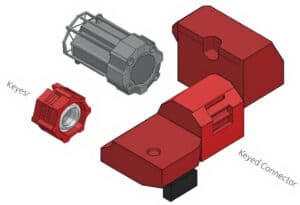
A part that can only physically go back together one way removes an entire category of reassembly error. Asymmetric screw boss spacing, a keyed connector shroud, or a single unique fastener length reserved for the one screw that must not be swapped with its neighbors are all low-cost geometric decisions that make correct reassembly the only reassembly, rather than relying on a label or an instruction sheet to prevent a mismatch. Where full asymmetry is impractical — four identical corner screws, for example — molded position numbers adjacent to each boss let a repairer track which screw came from where without extra hardware.
Tip: look at Poka-Yoke concepts and solutions also; many similarities

Consistent mounting and dismounting technique across a product line
Repair speed compounds across a product line when the removal technique is consistent: the same push-in, twist-release, or pull-tab motion used for a battery cover on one model and a filter cover on the next means a repairer’s learned motion transfers, and disassembly time on the second product benefits from experience gained on the first. This argues for a documented internal mechanism library at the company level — a small, standardized set of validated snap and latch geometries reused across products — rather than each program inventing its own release mechanism. It is also a manufacturing efficiency gain independent of repairability: fewer unique tool geometries in the mold shop, fewer unique fatigue-validation campaigns to run.
Point-of-use digital guidance
A molded or laser-etched QR code adjacent to the primary access point, linking directly to a model-specific teardown video or exploded-view guide, closes the gap between “this joint is physically simple” and “the user knows it is physically simple.” This only works if the guide it links to is versioned to the specific product revision — a generic teardown guide that does not match a mid-cycle running change in fastener count or type erodes trust in the whole system faster than having no guide at all. Right to Repair documentation obligations already require this content to exist for covered categories; placing a durable, on-product link to it is a near-zero-cost addition once the documentation itself is produced.
Tooling philosophy: standard, minimal, or none
The tool-dependency hierarchy from the fundamentals chapter has a practical corollary here: every step down from special tool to standard tool to tool-free is a step down in both disassembly time and in the population of people capable of performing the disassembly at all. A product should default to tool-free for anything expected to be opened by an end user (battery covers, filter access, expansion slots) and standard tool for anything expected to be opened by a repair technician but not routinely by the end user (mainboard access, internal module replacement), reserving no joint anywhere on the documented repair path for a special or proprietary tool. Where a specific tool genuinely is required — a suction cup for a bonded but debondable display, for instance — specifying and where possible including or referencing a widely available generic tool, rather than a proprietary one, keeps that joint from silently reintroducing a special-tool dependency.
iFixit’s teardown methodology, developed originally as an independent repairability audit rather than a manufacturer design tool, is worth studying directly because its scoring rewards exactly this layer: products lose points not only for adhesive and proprietary fasteners but explicitly for undocumented disassembly sequence and non-obvious release mechanisms, treating discoverability as a scored attribute rather than a footnote. Designing against that scoring rubric during development, rather than being scored by it after launch, is a straightforward way to pressure-test this chapter’s guidance before a product ships.
Tip: run a blind disassembly test with participants who have never seen the product, given no instructions beyond “open this and remove the battery,” and time them. Be the fly on the wall (see design and usability interview techniques). The gap between that time and the time achieved by an engineer familiar with the design is the actual measure of how well the visual and mechanical language communicates — and it is usually a larger gap than teams expect until they measure it.
Documentation, Material Marking, and the Spare-Parts Ecosystem

The physical design work in the preceding chapters only delivers its intended benefit if it is paired with the administrative and informational layer that lets a repairer, a recycler, or a regulator actually use it.
Repair documentationRight to Repair obligations require accessible repair information — typically exploded-view diagrams, torque specifications, and step-by-step procedures — for covered spare parts, made available to independent repairers on reasonable terms, not just to an authorized service network. This documentation needs to be generated from the same CAD and tolerance data used in production, not recreated separately by a technical writer working from photographs after the fact; doing so both reduces cost and eliminates the mismatch-with-reality problem that erodes trust in point-of-use QR guidance, discussed in the previous chapter. | Material marking for recyclersISO 11469 marking, molded directly into each part rather than printed on a label that can delaminate or be removed, should appear on every part above a minimum mass threshold (commonly cited industry practice is parts over roughly 25 grams, though this varies by jurisdiction and internal standard) and should be legible without disassembly aids where possible — on an external or easily-exposed face rather than buried against a mating surface. As noted in the mono-material chapter, this marking supports manual sorting and disassembly audits; it does not replace the underlying material-compatibility work. |
Spare-parts availability commitmentsRight to Repair and related national implementations set minimum windows — commonly in the range of seven to ten years from end of production, varying by product category and member state — during which spare parts must remain available at a reasonable price. This is a supply-chain and inventory planning commitment as much as a design one, but it feeds back into design directly: a spare part with a long-tail availability commitment needs a stable specification that will not be quietly superseded by an unannounced running change, because a repair manual referencing a part number that no longer matches what ships is a compliance gap as real as a missing joint specification. | Digital Product PassportESPR’s Digital Product Passport requirement, being phased in by product category, will formalize much of this into a machine-readable record attached to the product — material composition, disassembly instructions, spare-parts sourcing — accessible via a scannable identifier on the product itself. Designing the physical marking and QR guidance discussed in the intuitive-disassembly chapter with DPP compatibility in mind now avoids a second retrofit once category-specific DPP requirements take effect. |
Tip: assign a single internal owner for the repair-documentation-to-CAD synchronization process, with a defined trigger (any engineering change order affecting a documented joint or part automatically flags the corresponding manual page for review). Without an explicit owner and trigger, documentation drift after launch is close to guaranteed, since it is nobody’s job by default once a product ships.
Bonus: Business and Manufacturing Economics
DfD is frequently pitched internally as a compliance cost. The complete accounting is more favorable than that framing suggests, but it requires looking past unit assembly cost to the full life-cycle, harder for marketers and consumers …
Where the cost genuinely goes upSnap-fit and screw architectures generally carry a higher part count than a bonded or welded equivalent, which means more tooling cavities, more assembly-line stations, and more fastener purchasing and inventory overhead. Gasket-sealed enclosures need tighter dimensional tolerance control across the compression groove than an adhesive-sealed equivalent tolerates, which can mean tighter mold tolerances or additional in-process gauging. Debonding-on-demand adhesives, where used, cost meaningfully more per unit than standard structural adhesive. None of this is negligible, and a program that assumes DfD is cost-neutral at the unit level will be surprised by the actual bill of materials delta. | Where it is recoveredWarranty and out-of-warranty repair cost falls when a technician can reach a failed component in one or two steps instead of five, and falls further when a portion of repairs that previously required full-unit replacement (because the failed part was unreachable without destroying adjacent parts) become single-part repairs instead. Recycling-stream yield value rises measurably when housing mass exits as a single, unmixed, correctly identified resin stream rather than a mixed-material fraction that recyclers often down-cycle or landfill rather than process at a loss. Brand and procurement value is increasingly explicit rather than soft: public-sector and enterprise procurement in the EU is beginning to specify minimum repairability scores as a tender criterion, converting a DfD investment directly into addressable market rather than leaving it as a reputational externality. |
Future Trajectory as our Conclusion

Three developments will extend this article’s framework beyond where current products sit today:
- Digital Product Passports, once category-specific ESPR delegated acts finalize their requirements, will turn the documentation chapter’s manual-synchronization discipline into a real-time, auditable data feed rather than a periodically updated PDF, raising the cost of documentation drift and correspondingly raising the value of the CAD-to-documentation pipeline built now.
- Automated and robotic disassembly, still largely confined to pilot recycling facilities today, adds a second audience beyond the human repairer and recycler this article has focused on: a robotic disassembly cell needs machine-legible joint locations and consistent, predictable release geometry even more than a human technician does, which will likely push the visual-language and geometric-consistency principles from the intuitive-disassembly chapter toward formal, machine-readable standards rather than the largely convention-driven practice they are today.
- Chemical recycling routes, which can in principle handle some mixed-polymer streams that mechanical recycling cannot, may eventually relax the strict mono-material requirement in Pillar Two for specific resin combinations — but chemical recycling capacity remains a small fraction of total plastics recycling volume, and designing against its eventual availability rather than against mechanical recycling’s current, dominant reality is a bet most product programs cannot responsibly make yet.
The through-line across all of it is the same one this article opened with: disassembly stopped being an edge case the day regulation made it a measured, audited product attribute.
The enclosures that will age well over the next regulatory cycle are the ones where snap-fit architecture, mono-material resin selection, adhesive elimination and legible disassembly sequencing were treated as one integrated design problem from the concept phase, not four separate checklist items reconciled at the end.
External Links on Design for Disassembly
International Standards
(hover the link to see our description of the content)
Glossary of Terms Used
Bill Of Material (BOM): a structured list detailing the components, subassemblies, and raw materials required to manufacture a product, including quantities and specifications, used for production planning and inventory management.
Bill of Materials (BOM): a comprehensive list detailing the components, materials, and quantities required to manufacture a product, often used in manufacturing and engineering to facilitate production planning, inventory management, and cost estimation.
Computer Aided Design (CAD): a software application used for creating, modifying, analyzing, and optimizing designs in various fields such as engineering, architecture, and manufacturing, enabling precise drawings and models through digital tools and techniques.
Computer-Aided Design (CAD): a software application used for creating, modifying, analyzing, and optimizing designs in various fields such as engineering, architecture, and manufacturing, enabling precise drawings and models through digital tools and techniques.
Design for Disassembly (DfD): a design approach that facilitates the easy separation of components and materials at the end of a product's life cycle, promoting recycling, reuse, and efficient waste management. It emphasizes modularity and accessibility to enhance sustainability and reduce environmental impact.
Design for Manufacturing (DfM): a set of principles aimed at simplifying and optimizing product designs to enhance manufacturability, reduce production costs, and improve quality by considering manufacturing processes, materials, and assembly techniques during the design phase.
Engineering Change Order (ECO): a document that authorizes modifications to a product's design, specifications, or processes, detailing the changes, reasons, and implementation instructions, ensuring proper tracking and management of alterations throughout the product lifecycle.
Finite Element Analysis (FEA): a numerical method for solving complex engineering problems by breaking down structures into smaller, simpler parts called elements, allowing for the analysis of stress, strain, and deformation under various conditions.
International Organization for Standardization (ISO): a non-governmental international body that develops and publishes standards to ensure quality, safety, efficiency, and interoperability across various industries and sectors, facilitating global trade and cooperation. Established in 1947, it comprises national standardization organizations from member countries.
Metal Active Gas (welding) (MAG): a welding process that uses a continuously fed consumable electrode and a shielding gas mixture, typically containing carbon dioxide, to protect the weld pool from atmospheric contamination during the joining of ferrous and non-ferrous metals.
Metal Inert Gas (welding) (MIG): a welding process that uses a continuous solid wire electrode fed through a welding gun, creating an electric arc between the wire and the workpiece, melting both to form a weld pool, typically shielded by an inert gas to prevent contamination.
Positive Material Identification (PMI): a process used to verify the composition of materials, typically metals, through non-destructive testing techniques such as X-ray fluorescence or optical emission spectroscopy, ensuring compliance with specifications and preventing material mix-ups in manufacturing and construction.
Printed Circuit Board (PCB): a flat board made of insulating material that supports and connects electronic components through conductive pathways, typically etched from copper sheets. It serves as a foundation for circuit assembly and facilitates electrical connections between components.
Probability Density Function (PDF): a function that describes the likelihood of a continuous random variable taking on a specific value, where the area under the curve over an interval represents the probability of the variable falling within that interval.
Waste Electrical and Electronic Equipment (WEEE): discarded electrical and electronic devices, including components, assemblies, and subassemblies, that are no longer in use or functional, posing environmental hazards if not properly managed. Includes items such as computers, televisions, and appliances.