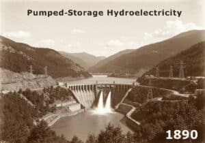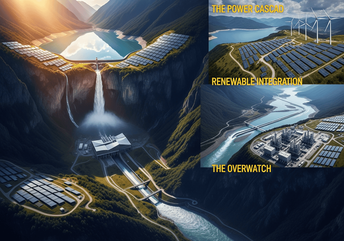
Pumped-storage hydroelectricity stores electrical energy by moving water uphill and recovering it later through turbines on the way back down. It is the oldest grid-scale storage technology in commercial use, with roots in 1890s Alpine Europe, and it remains the largest by installed capacity even as battery deployment grows rapidly worldwide. The technology scaled globally in the mid-twentieth century to balance inflexible nuclear baseload generation, and over the past two decades its function has shifted toward absorbing the variability of wind and solar output, a role that depends on the same core physics: gravitational potential energy converted to and from electricity through a reversible pump-turbine.
Our article hereafter covers the full technical and economic scope of PSH: the underlying physics and efficiency limits, the electromechanical architecture that makes reversible operation possible, the grid-stability services the technology provides beyond simple energy storage, its operational strategies and revenue mechanisms, the environmental constraints that shape where projects get built, emerging configurations like underground and seawater PSH, the regulatory frameworks governing its deployment, and a direct comparison against batteries, compressed air, flow batteries, hydrogen, and flywheels across the criteria that matter for real investment and planning decisions.
Key Takeaways
- PSH is the oldest and still the largest grid-scale storage technology: dating back to 1890s Alpine Europe, it remains the dominant storage technology by installed capacity worldwide, even as battery deployment accelerates.
Its physics are simple, but its footprint is enormous. Energy storage scales with mass, gravity, and height (\(E = \eta , m , g , h\)), but because water has such low energy density compared to chemical batteries, PSH needs reservoirs measured in millions of cubic meters to store what a battery could hold in a warehouse. - Head versus flow drives the entire engineering design: high-head mountain sites use compact Francis-type machines; low-head river sites need massive Kaplan-type turbines moving huge water volumes — the site’s geography dictates the technology, not the other way around.
- Round-trip efficiency typically runs 70–85%, slightly lower than modern lithium-ion batteries (85–95%), but PSH sustains that performance over 50–100 years rather than the 10–20 years before a battery needs replacing.
- PSH does more than store energy — it stabilizes the grid. Its spinning mass provides physical inertia, it delivers fast frequency regulation, it can act as a synchronous condenser for voltage support without moving water, and it’s one of the few technologies capable of black-starting a collapsed grid.
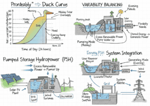
- Its role has shifted from “peak shaving” to “variability balancing.” Built originally to pair with inflexible nuclear baseload, PSH today mainly absorbs the steep ramps of solar and wind — most visibly the “duck curve” — making it a critical renewable-integration asset.
- Environmental management is a first-order design issue, not an afterthought. Closed-loop (off-river) configurations, sediment control, evaporation mitigation, and water-quality/thermal management all shape where and how new PSH projects get built and permitted.
- New frontiers are expanding where PSH can be built. Underground PSH (mines, caverns), seawater PSH, hybrid energy parks combining floating solar with reservoirs, and small-modular designs are all working to overcome PSH’s traditional dependence on rare, large-elevation-difference sites.
- PSH complements rather than competes with other storage technologies. It owns the long-duration, high-reliability, grid-inertia niche; batteries dominate fast response and short duration; hydrogen leads on seasonal storage. The future grid needs a diversified portfolio, not a single winning technology.
Foundations and Historical Evolution

Pumped-storage hydroelectricity (PSH), also known as pumped hydro storage or pumped hydroelectric energy storage (PHES), is the oldest and by far the largest form of grid-scale energy storage in the world today. At its core, the technology is deceptively simple: water is pumped uphill into a reservoir when electricity is cheap or abundant, and released downhill through turbines to generate electricity when it is scarce or expensive. This simple mechanical principle has made PSH the backbone of grid-scale storage for more than a century, and it remains the dominant storage technology by installed capacity even in an era of rapidly falling battery costs.
PSH is often described informally as a “water battery.”
Unlike a chemical battery, which stores energy in the electrochemical bonds of its active materials, a pumped-storage plant stores energy in the gravitational potential of an elevated mass of water. The analogy is useful but imperfect: a water battery does not degrade chemically over thousands of cycles the way a lithium-ion cell does, but it is bound by geography, the availability of suitable terrain and water rights, and a vastly larger physical footprint and construction timeline. Where a battery factory can be built in two years, a pumped-storage scheme can take a decade or more from initial site studies to commissioning. This trade-off between deployment speed and asset longevity is central to understanding PSH’s role in modern grids.
Early Origins (1890s–1920s)The first pumped-storage installations emerged in the Alpine regions of Europe in the final decade of the nineteenth century. Switzerland, Italy, and parts of southern Germany possessed two ingredients that made early PSH viable: abundant mountain topography offering large elevation differences over short distances, and a nascent electricity industry struggling with the mismatch between continuous hydroelectric generation and fluctuating industrial demand. Early industrial loads, dominated by tramways, textile mills, and emerging municipal lighting networks, were highly variable throughout the day, while many of the run-of-river and lake-fed hydro stations of the period produced relatively steady output. Pumped storage offered a way to bank surplus generation during low-demand hours and redeploy it during peak demand, smoothing the mismatch without requiring additional fuel-based capacity. These first-generation schemes were modest by modern standards, typically built around a single reversible or paired pump-and-turbine arrangement, with storage capacities measured in the tens rather than thousands of megawatt-hours. Nonetheless, they established the foundational logic that still defines the technology today: use cheap or surplus energy to lift water, recover a portion of that energy later as electricity, and profit from or otherwise exploit the difference in value between the two time periods. | The Nuclear Era Symbiosis (1960s–1980s)The technology’s first great expansion came in the decades following the Second World War, as nations rebuilt and electrified their economies and as nuclear power emerged as a major source of baseload generation. Nuclear plants are technically and economically suited to running at a constant output level; ramping a reactor up and down quickly is both mechanically stressful and economically wasteful, since the fuel cost is a small fraction of a nuclear plant’s overall cost structure compared to the enormous fixed capital cost. This created a structural problem: nuclear output is most efficient when flat, but electricity demand is never flat. It rises sharply in the morning and evening and falls to a trough overnight. Pumped storage became the natural partner technology for nuclear baseload generation during this period. Utilities in France, Japan, the United States, and the United Kingdom built large PSH stations specifically to absorb the nighttime surplus from nuclear (and to a lesser extent coal) plants that could not be economically throttled down. This surplus energy, which would otherwise have been curtailed or sold at a loss, was instead used to pump water uphill overnight. The following day, during the morning and evening demand peaks, that stored water was released to generate electricity, effectively allowing nuclear plants to operate at their efficient constant output while the grid still received a variable power profile matching demand. This relationship is sometimes referred to as the “nuclear-pumped storage symbiosis,” and it explains why countries with large nuclear fleets, such as France, Japan, and the United States, also tend to have large fleets of pumped-storage plants built during this same multi-decade window. |
The Renewable Pivot (21st Century)

The role of pumped storage has shifted substantially since the early 2000s with the large-scale deployment of wind and solar generation. Where the twentieth-century use case was “peak shaving” — smoothing a known, fairly predictable daily demand curve against a known, fairly predictable baseload supply curve — the twenty-first-century use case has become “variability balancing”: absorbing the much less predictable, weather-driven fluctuations of renewable output.
Solar generation, for instance, produces a sharp midday surge followed by a steep evening decline as the sun sets, often coinciding precisely with the evening demand peak. This has given rise to the now-famous “duck curve” phenomenon in grids with high solar penetration, where net demand (total demand minus renewable supply) dips deeply in the middle of the day and then ramps extremely steeply in the early evening. Wind generation, meanwhile, can swing significantly over the course of hours or days based on weather systems, with little correlation to demand patterns. Pumped storage, with its ability to absorb large amounts of power for charging and to ramp to full output in a matter of seconds to a few minutes, has proven well suited to managing both of these renewable-driven variability patterns, even though the technology itself was not originally designed with renewables in mind.
Global Distribution
The global map of pumped-storage capacity closely traces the history just described. Japan built an enormous PSH fleet from the 1960s onward, driven by its heavy reliance on nuclear power and its mountainous geography, and remains one of the largest PSH markets in the world. Europe’s PSH capacity is concentrated in the Alpine nations (Switzerland, Austria, Italy) and in countries that pursued large nuclear programs (France), alongside significant capacity in Spain, Germany, and the Nordic countries. The United States built a substantial fleet during the 1970s and 1980s, much of it linked to the nuclear buildout of that era, with major installations in the Appalachian region, the Pacific Northwest, and California. More recently, China has become the largest single national market for new pumped-storage construction, driven by its enormous and rapidly growing renewable energy capacity and a national strategic push for grid-balancing infrastructure.
The Physics of Gravitational Energy Storage
Energy Density Modeling
The fundamental physics of pumped storage rests on the conversion between gravitational potential energy and electrical energy. The stored potential energy of a mass of water held at an elevation above a lower reservoir is given by the classic gravitational potential energy equation, adjusted for the round-trip efficiency of the overall system:
| \(E = \eta \, m \, g \, h\) | where
|
Because water has a fixed density of approximately 1,000 kilograms per cubic meter, this equation can be rewritten in terms of reservoir volume rather than mass, which is more useful for engineering and site-planning purposes: \(E = \eta \, \rho \, V \, g \, h\)
where \(\rho\) is the density of water and \(V\) is the volume of water cycled between reservoirs. This formulation immediately reveals the central design trade-off of pumped storage:
total energy storage capacity scales linearly with both the volume of water available and the head height, meaning that a site with twice the head can store the same energy with half the reservoir volume, and vice versa.
This is why high-head Alpine and mountainous sites, which can offer 500 to over 1,000 meters of elevation difference, can achieve enormous energy storage capacities with comparatively small reservoirs, while low-head sites need vastly larger reservoir volumes to store a comparable amount of energy.
When compared to chemical battery storage on a volumetric basis, pumped hydro is strikingly energy-sparse. A typical lithium-ion battery system can store on the order of several hundred watt-hours per liter of cell volume, whereas a cubic meter (1,000 liters) of water raised 500 meters, even at a generous 85 percent round-trip efficiency, stores only around 1.16 kilowatt-hours, or roughly 1.16 watt-hours per liter.
- This vast difference in volumetric energy density is precisely why pumped storage requires reservoirs measured in the millions of cubic meters and footprints measured in square kilometers, while a battery installation storing the same total energy might fit inside a single warehouse.
- The trade-off is that the underlying “active material” for PSH, water and gravity, costs essentially nothing and does not degrade, whereas battery active materials are manufactured, finite in cycle life, and represent a continuing capital cost as they degrade and require eventual replacement.
Practical tip: when sizing a project from scratch, it is far more useful to invert the energy equation and solve for required reservoir volume given a target energy capacity and the head available at the candidate site, rather than starting from a fixed reservoir size and seeing what energy capacity results. Site selection in practice almost always starts with the question “how much head do we have,” since head is fixed by geography, while reservoir volume is the one variable that civil engineers can still adjust through dam height, basin excavation, or footprint.
The Bath County Pumped Storage Station in Virginia, one of the largest PSH facilities in the world, pairs a roughly 380-meter head with a combined reservoir volume large enough to support about 3,000 megawatts of capacity and roughly 24,000 megawatt-hours of storage, illustrating how a comparatively modest, non-extreme head, when combined with very large reservoirs, can still deliver utility-scale storage on par with the largest battery installations ever built, but at a duration measured in many hours rather than the one-to-four-hour duration typical of grid-scale battery projects.
The “Head vs. Flow” Relationship
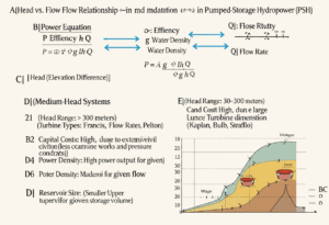
Beyond total energy storage, the power output of a pumped-storage plant, meaning the rate at which it can deliver energy, depends on a different relationship: the product of head and the volumetric flow rate of water through the turbines. This is expressed as: \(P = \eta \, \rho \, g \, h \, Q\)
where \(P\) is instantaneous power (in watts) and \(Q\) is the volumetric flow rate (in cubic meters per second). This equation drives one of the most consequential engineering decisions in PSH design: whether to pursue a high-head or low-head configuration, and which turbine technology follows from that choice.
High-head systems, generally defined as sites with more than roughly 150 to 200 meters of elevation difference, can generate substantial power with relatively modest flow rates, because the head term in the power equation does most of the work. This allows for smaller, faster-spinning turbines and smaller-diameter penstocks (the pressurized pipes carrying water to the turbines), which in turn reduces capital costs per unit of installed capacity for the waterway infrastructure, even though high-head sites are typically located in mountainous terrain that increases tunneling and civil works costs. Francis-type reversible pump-turbines dominate this category, as their radial-flow design handles high pressures efficiently.
Low-head systems, typically found on rivers or in flatter terrain with elevation differences of less than 30 to 50 meters, must move enormous volumes of water to achieve meaningful power output, since the head term contributes comparatively little. This drives the use of large-diameter, slower-spinning axial-flow turbines, most commonly Kaplan-type units adapted for reversible pump-turbine operation, or in some very low-head applications, bulb-type turbines. Low-head plants tend to have larger physical footprints for their waterways and powerhouses relative to their power output, but they can be sited in regions without dramatic mountain topography, broadening the geographic range of viable PSH development. Between these two extremes, medium-head sites, generally in the range of 50 to 150 meters, often use Francis-type machines as well, though the specific runner geometry is tuned differently than for high-head applications to balance efficiency across the flow range the plant is expected to operate within.
Basic rule of thumb: when roughly comparing competing sites at the feasibility stage, experienced developers favor a quick head-to-distance ratio screening calculation before committing to detailed engineering studies; a ratio above roughly 1:10 (one meter of vertical head for every ten meters of horizontal separation between reservoirs) is generally considered attractive, since it keeps waterway tunnel or penstock lengths, and therefore civil costs, manageable relative to the head captured.
Thermodynamics of the Cycle
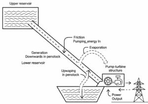
No real pumped-storage cycle achieves the idealized energy conversion suggested by the basic potential energy equation. Energy is lost at multiple stages of the pumping-generating cycle, and understanding where these losses occur is essential to understanding both plant design and the realistic performance limits of the technology.
Engineers who document this equation in reports often typeset it with LaTeX, and a LaTeX cheat sheet shows how to write the fractions, Greek letters and subscripts of the efficiency formula, while a LaTeX math cheat sheet covers the rest of the notation.
- The largest category of loss is fluid friction, which occurs as water moves through penstocks, tunnels, and the internal passages of the pump-turbine itself. Friction losses scale with the square of flow velocity, meaning that doubling the flow rate through a given pipe roughly quadruples the frictional pressure loss, which is why waterway designers favor larger-diameter tunnels and penstocks even though they cost more to excavate or fabricate, since the energy losses avoided over decades of operation typically justify the larger upfront capital expenditure. Friction losses are present in both the pumping direction and the generating direction, meaning they reduce round-trip efficiency twice over: once as the plant works harder than theoretically necessary to push water uphill, and again as some of the water’s potential energy is dissipated as heat rather than converted to electricity on the way back down.
- A second category of loss occurs within the electromechanical conversion chain itself: hydraulic losses within the pump-turbine runner (where the geometry of the blades cannot perfectly match the flow conditions across all operating points), mechanical losses in bearings and seals, and electrical losses in the generator-motor windings, transformers, and associated switchgear. These losses are typically smaller in proportion than waterway friction losses in well-designed modern plants but are nonetheless significant, particularly because the same machine must perform efficiently in two very different operating modes (pumping and generating) with different optimal blade angles and flow characteristics.
- A third, smaller category of loss is evaporation from the open reservoir surfaces, which represents a loss of the working fluid itself rather than an energy conversion inefficiency in the traditional sense, but which nonetheless reduces the net energy available for future cycles and requires make-up water to be added over time. This loss is highly site-specific and climate-dependent, ranging from negligible in cool, humid climates to a serious operational and environmental concern in arid regions, a topic explored in further chapter.
Round-Trip Efficiency (RTE)
The cumulative effect of all these losses is captured in the round-trip efficiency metric, often described using the shorthand “wire-to-water-to-wire” efficiency, meaning the fraction of electrical energy drawn from the grid during pumping that is ultimately returned to the grid during generation. Modern, well-designed pumped-storage plants typically achieve round-trip efficiencies in the range of 70 to 85 percent, with the most modern variable-speed installations using advanced reversible pump-turbines at the higher end of this range, and older fixed-speed or less optimally sited plants nearer the lower end.
This range positions pumped storage as broadly competitive with, though generally somewhat lower than, the round-trip efficiency of modern lithium-ion battery systems, which often achieve round-trip efficiencies in the 85 to 95 percent range at the cell level (system-level efficiency, including inverter and thermal management losses, is somewhat lower). However, the comparison is not purely about efficiency:
- pumped-storage plants can sustain this efficiency over an operational lifespan measured in decades, often 50 to 100 years for the civil infrastructure, with periodic refurbishment of the electromechanical components, whereas battery systems experience gradual capacity and efficiency degradation over a much shorter cycle life, typically measured in thousands of cycles or 10 to 20 years before significant capacity loss requires replacement.
- and pumped-storage plants can retain the energy (ie the water) almost indefinitely
Tip: when evaluating a plant’s published round-trip efficiency figure, always check whether it is quoted at the design flow point or averaged across the full operating range, since pump-turbines lose efficiency markedly at partial load; a unit rated at 80 percent RTE at full flow may deliver closer to 70 percent when operating at 40 percent of rated flow, which matters considerably for plants increasingly asked to follow variable renewable output rather than run at a fixed design point.
Grid Integration & Synchronous Services

Beyond storing and discharging energy, pumped-storage plants perform a second, equally critical function: keeping the electricity grid itself stable from second to second. This comes from the physical nature of the equipment rather than from the water in the reservoirs. A large synchronous motor-generator spinning at grid frequency behaves like a flywheel, automatically resisting sudden frequency disturbances, and the same machine can supply reactive power for voltage support or restart a collapsed grid from scratch, all independent of whether the plant is actively pumping or generating at that moment.
This chapter examines four distinct grid-services that pumped-storage hydroelectricity provides:
- the passive inertial stabilization delivered automatically by rotating mass,
- the active frequency regulation performed through fast-acting control systems,
- the voltage support achieved through synchronous-condenser operation with no water movement at all,
- and the black-start capability that makes PSH one of the few technologies able to bootstrap a fully de-energized grid.
As wind and solar generation, connected through inverters rather than spinning machines, displace conventional synchronous generation, these services have shifted from a secondary benefit of PSH plants to one of the primary reasons grid operators value them.
Physical Rotating InertiaOne of the most operationally important, and frequently underappreciated, contributions of pumped-storage plants to grid stability has nothing to do with the energy stored in their reservoirs at all: it is the physical rotating inertia of their large synchronous motor-generators. The rotor of a pumped-storage unit, typically a steel and copper assembly weighing many tonnes and spinning at a fixed multiple of grid frequency, stores kinetic energy in its rotation in direct proportion to its moment of inertia and the square of its rotational speed. This stored kinetic energy matters because, in the event of a sudden imbalance between electricity supply and demand on the grid, such as the unexpected loss of a large generator or a sudden surge in demand, the grid frequency will begin to drift away from its nominal value (50 or 60 hertz) within fractions of a second, well before any control system or automated response mechanism can react. Large rotating masses connected synchronously to the grid, including but not limited to pumped-storage units, instinctively resist this frequency change through simple Newtonian physics: as grid frequency dips, the rotating mass of every synchronously connected machine naturally gives up some of its kinetic energy to help arrest the decline, slowing the rate of frequency change and buying crucial time for automatic and manual control systems to respond. This inertial contribution has become increasingly significant as grids have added large amounts of wind and solar generation, much of which is connected to the grid through power-electronic inverters rather than directly coupled rotating machines, and which therefore contributes comparatively little natural inertia. Grid operators in regions with high renewable penetration, such as Ireland, the United Kingdom, South Australia, and parts of the United States, have identified declining system inertia as a genuine operational risk, since lower-inertia grids experience faster and larger frequency excursions following any given disturbance, increasing the risk of cascading equipment trips or, in extreme cases, system-wide blackouts. | Frequency RegulationBeyond the passive, physics-based contribution of rotating inertia, pumped-storage plants also provide active frequency regulation services, in which the plant’s control systems deliberately adjust power output (or pumping consumption) in response to measured deviations in grid frequency. These services are conventionally divided into primary and secondary response categories, though exact terminology and timing requirements vary somewhat between grid operators and regulatory regions.
|
Voltage Support & Reactive PowerPumped-storage plants can also provide grid voltage support through reactive power management, a service that, notably, can be delivered without any net movement of water at all. Electrical power flowing through an alternating current grid has two components: real power, measured in watts, which performs useful work such as lighting a building or running a motor, and reactive power, measured in volt-amperes reactive (VAR), which does not perform useful work directly but is essential to maintaining the correct voltage levels throughout the transmission and distribution network. Reactive power demand on a grid arises from the inductive and capacitive characteristics of transmission lines, transformers, and many types of load equipment, and an imbalance in reactive power supply and demand causes voltage levels to drift outside acceptable operating ranges, risking equipment damage or instability. A pumped-storage unit’s synchronous motor-generator can be operated in a mode known as a synchronous condenser, in which the machine remains spinning and electrically connected to the grid, absorbing or supplying reactive power as needed to support local voltage levels, while consuming only the small amount of real power needed to overcome friction and other losses in keeping the rotor spinning, and without pumping or generating any net flow of water through the hydraulic system at all. This capability is particularly valuable at pumped-storage sites located at strategically important points on the transmission network, since it allows the plant to provide a continuous, around-the-clock grid-support service that does not draw down the reservoir or compete with the plant’s primary energy-arbitrage role, effectively offering grid operators a “free” additional service from infrastructure that would otherwise be idle during off-peak hours when the plant is not pumping or generating. | Black Start CapabilityPerhaps the most dramatic grid-service role that pumped-storage plants can fulfill is black start capability: The ability to restart and re-energize a portion of the electricity grid following a total system collapse or blackout, in which no external power source is available anywhere on the network to bootstrap the restoration process. This is a uniquely demanding requirement, since most types of generation, including most thermal power stations, require an external electricity supply of their own (for items such as cooling pumps, control systems, fuel handling equipment, and start-up motors) before they can begin generating, creating a chicken-and-egg problem during a full system blackout. Pumped-storage plants are among the relatively small set of generation technologies capable of providing black start service, because a unit with water available in its upper reservoir can begin generating power using only locally stored energy (in the form of station batteries or small diesel generators) to operate its own essential control and auxiliary systems, with no need for an external grid connection to get started. The technical sequence of a black start typically involves first using these local auxiliary power sources to open the appropriate gates and valves and bring the unit’s basic control systems online, then opening the wicket gates to allow water to begin flowing through the turbine runner, bringing the unit up to synchronous speed in island mode (meaning electrically isolated, supplying only its own immediate local auxiliary loads and perhaps a small initial “cranking path” of nearby transmission infrastructure), and then gradually expanding the energized portion of the grid outward from this initial island. |

Hydrological & Environmental Management
Closed-Loop vs. Open-Loop Systems
Pumped-storage plants are generally classified into two broad hydrological categories based on their relationship to natural waterways. Closed-loop, or “off-river,” systems are designed so that both the upper and lower reservoirs are hydrologically isolated from any natural river, stream, or other continuously flowing water body, typically located in elevated terrain away from natural drainage systems and filled initially with water drawn from groundwater, a nearby river, or other water source, but thereafter operated as a largely self-contained loop with minimal ongoing interaction with natural aquatic ecosystems. Open-loop systems, by contrast, have at least one reservoir, usually the lower reservoir, directly connected to a natural river or other waterway, with water continuously or periodically exchanged between the pumped-storage system and the natural watercourse.
This distinction carries significant environmental and regulatory implications.
- Closed-loop systems generally face a substantially simpler environmental permitting and ongoing regulatory process, since they avoid many of the direct ecological interactions, such as fish passage, sediment transport disruption, and altered downstream flow regimes, that arise when a project is directly connected to a living river system.
- Open-loop systems, while sometimes offering site advantages such as more reliable water availability or proximity to existing infrastructure, generally require more extensive environmental impact assessment and ongoing monitoring and mitigation measures, addressing concerns such as fish entrainment in pump and turbine intakes, changes to natural flow variability that downstream ecosystems may depend on, and water quality changes in the connected river system.
This distinction has become increasingly important in site selection for new pumped-storage projects, with closed-loop, off-river configurations often favored in jurisdictions with stringent river ecosystem protections, even when this requires more extensive pipeline or tunnel infrastructure to connect the site to an external water source for initial filling and make-up water.
Water Quality & Thermal ManagementThe repeated cycling of large volumes of water between an upper and lower reservoir, often with significant elevation and corresponding pressure and temperature changes, can create water quality management challenges distinct from those of a conventional, non-pumped reservoir. One significant concern is stratification and oxygenation: reservoirs, particularly larger and deeper ones, can naturally develop distinct temperature layers, with cooler, denser water settling toward the bottom and warmer water remaining near the surface, and these layers can have markedly different dissolved oxygen concentrations, with bottom layers sometimes becoming oxygen-depleted if not adequately mixed. The pumping and generating cycle of a pumped-storage plant tends to actively mix reservoir water far more than would occur naturally, which can be either beneficial or detrimental to water quality and downstream ecology depending on the specific characteristics of the site. Active mixing can help oxygenate water that would otherwise stagnate, but it can also disrupt natural thermal stratification patterns that some aquatic species depend on for habitat and reproduction, or it can mobilize sediments and nutrients from the reservoir bottom into the water column, requiring careful site-specific environmental management. | Sediment and SiltationSediment accumulation represents one of the more persistent operational and maintenance challenges for pumped-storage facilities, particularly open-loop systems connected to rivers carrying natural sediment loads. Suspended sediment entering the system through intake structures can accumulate in reservoirs over time, gradually reducing usable storage volume, and perhaps more significantly from an equipment perspective, can cause abrasive erosion damage to the precisely machined surfaces of pump-turbine runners, wicket gates, and other components exposed to high-velocity water flow. This erosion is a particular concern for pumped-storage plants compared to conventional, one-directional hydroelectric turbines, because reversible pump-turbines experience sediment-laden flow passing through their internal passages in both directions across the pumping and generating cycle, effectively doubling the opportunity for abrasive wear compared to a turbine that only ever sees flow moving in a single direction. Mitigation strategies commonly employed at pumped-storage sites include sediment-settling basins or forebays positioned upstream of the intake structures to allow coarser sediment particles to settle out of the flow before reaching the turbine, specialized hard-coating or hardened-alloy materials applied to runner surfaces and other components most exposed to erosive wear, and periodic reservoir dredging or flushing operations to remove accumulated sediment before it can significantly reduce storage capacity or be drawn into the intake system during operation. |
Evaporation Mitigation
Evaporative water loss from the open surface of pumped-storage reservoirs represents both an operational concern (since lost water must be replaced with make-up water to maintain the system’s storage capacity, as noted in Chapter 1) and, in water-scarce regions, a broader environmental and social concern given the competing demands on limited freshwater resources from agriculture, drinking water supply, and other uses. Evaporation rates depend heavily on local climate, with arid and semi-arid regions experiencing substantially higher evaporative losses than cooler, more humid climates, and can represent a meaningful fraction of total reservoir water loss in the most challenging climates.
Several engineering approaches have been developed or proposed to mitigate evaporative losses at pumped-storage sites in arid climates. Floating cover systems, including floating solar photovoltaic panels (discussed further in the chapter about hybrid energy parks) or dedicated floating shade structures, can substantially reduce the surface area of open water directly exposed to sun and wind, the two primary drivers of evaporation. Reservoir design choices, such as favoring deeper reservoirs with a smaller surface area for a given storage volume over shallower, more spread-out designs, can also reduce the surface-area-to-volume ratio and correspondingly reduce evaporative losses. In the most water-constrained locations, some developers have explored using underground or partially enclosed reservoir configurations specifically to minimize evaporative exposure, an approach that overlaps significantly with the underground pumped-storage concepts discussed in the following chapter.
PSH Future & Hybridization
Underground PSH (UPSH)

One of the most actively explored frontiers in pumped-storage development is underground pumped-storage hydroelectricity, in which the lower reservoir of the system is located not at the surface but within an abandoned mine, a constructed salt cavern, or another deep geological void, with the upper reservoir typically remaining at or near the surface. This configuration directly addresses one of the most persistent constraints on conventional PSH development: the requirement for two geographically suitable reservoir sites with substantial elevation difference, a requirement that severely limits the number of viable sites in many densely populated or topographically flat regions.
By using a deep underground void as the lower reservoir, underground pumped storage can achieve very large heads, in some proposed configurations exceeding what would be achievable using only natural surface topography, while dramatically reducing the surface land footprint of the project compared to a conventional twin-surface-reservoir configuration. Abandoned mines are a particularly attractive option for this approach in many regions, since they often already possess much of the underground excavation and shaft infrastructure needed, potentially reducing construction costs relative to purpose-built underground caverns, while also offering a constructive afterlife for industrial sites that might otherwise remain unused following the end of mining operations. Significant engineering challenges remain in this emerging category, including ensuring the long-term structural stability of the underground void under the cyclic pressure loading associated with pumped-storage operation, managing groundwater interactions, and addressing the practical challenges of installing and maintaining large electromechanical equipment deep underground.
Seawater PSH
Another frontier configuration uses the ocean itself as the lower reservoir, a concept generally referred to as seawater pumped-storage hydroelectricity. This approach offers a potentially significant expansion of viable PSH sites, particularly for coastal and island regions with limited inland topography suitable for conventional twin-freshwater-reservoir configurations, since it only requires identifying a single elevated upper reservoir site near the coastline, with the sea serving as an essentially unlimited and already-present lower reservoir.
Additionally to the geographic challenge -mountain directly on the coast-, the principal engineering challenge specific to seawater pumped-storage is materials science: every component of the system that comes into contact with seawater, including pump-turbine runners, penstocks, valves, and any submerged structural elements, must be specifically engineered to resist the highly corrosive effects of saltwater over the multi-decade operational lifespan expected of pumped-storage infrastructure, typically requiring specialized corrosion-resistant alloys, protective coatings, or cathodic protection systems considerably more robust than those needed for freshwater applications. A second significant challenge is biofouling, the accumulation of marine organisms such as barnacles, mussels, and algae on submerged surfaces and within intake structures, which can reduce hydraulic efficiency, increase maintenance requirements, and in severe cases partially obstruct flow passages, requiring dedicated biofouling management strategies such as periodic mechanical cleaning, specialized antifouling coatings, or chemical treatment of intake water, all of which add operational complexity and cost relative to a conventional freshwater facility.

Hybrid Energy Parks
A growing trend in pumped-storage development involves the deliberate co-location of PSH facilities with other renewable generation technologies, most commonly floating solar photovoltaic (F-PV) installations placed directly on the surface of the reservoirs, or onshore wind farms sited near the PSH facility, creating an integrated hybrid energy park that shares transmission infrastructure and, in the case of floating solar, can deliver meaningful secondary benefits to the pumped-storage operation itself.
Floating solar panels installed on a pumped-storage reservoir surface can substantially reduce evaporative water loss, as discussed in the next chapter, by shading the water surface from direct sunlight, while simultaneously generating additional electricity that can be used directly to power the site’s pumping operations or exported to the grid, all without requiring additional land acquisition beyond the reservoir footprint that the PSH project already occupies. The shared use of grid interconnection infrastructure, including transmission lines, substations, and grid connection rights that can represent a significant portion of overall project cost and development time, allows these hybrid configurations to improve the overall economics of both the storage and the generation components compared to developing each separately at different locations. Co-location with wind farms offers a related but distinct benefit: since wind generation is often poorly correlated in time with solar generation and with overall electricity demand, having both wind generation and pumped storage at a single integrated site can allow more efficient use of the shared transmission capacity, with the pumped-storage facility absorbing wind output during periods when generation exceeds what the transmission link can carry to the wider grid, then releasing that stored energy later when transmission capacity becomes available.
To keep in mind: developers considering floating solar on an existing or planned PSH reservoir should account for the operational impact of fluctuating reservoir water levels on the floating array’s mooring and anchoring system design, since a reservoir that can be drawn down by tens of meters over each single generating cycle places very different mechanical demands on floating infrastructure than the comparatively stable water levels typical of a conventional irrigation or water-supply reservoir where most floating solar engineering experience has historically been built up.
Small-Modular PSH
A final emerging frontier involves the development of small-modular pumped-storage units: standardized, factory-manufactured, “plug-and-play” PSH systems designed for rapid deployment at a much smaller scale than the traditional large, custom-engineered, site-specific pumped-storage plants that have historically dominated the technology. Where conventional large-scale PSH projects typically require many years of bespoke civil engineering design tailored to the specific topography, geology, and hydrology of each individual site, small-modular PSH systems aim to standardize much of the electromechanical equipment and even portions of the reservoir or containment design into repeatable, pre-engineered modules that can be manufactured off-site and assembled relatively quickly at a range of different locations.
Comparative Analysis Against Other Storage Technologies

No storage technology exists in isolation, and a complete technical understanding of pumped-storage hydroelectricity requires placing it directly alongside the other major categories of grid-scale energy storage competing for the same investment dollars and the same role in modern electricity systems. The most relevant points of comparison are:
- lithium-ion battery energy storage systems (BESS), now the fastest-growing storage category worldwide
- compressed air energy storage (CAES), a mechanical storage technology that shares some conceptual similarities with PSH
- flow batteries, an emerging electrochemical technology specifically aimed at longer-duration applications
- hydrogen-based storage, which converts surplus electricity into hydrogen for later reconversion to power or other uses
- flywheel energy storage, a purely mechanical, very short-duration technology.
Each of these technologies has a distinct combination of strengths and weaknesses across dimensions including duration, efficiency, cost, lifespan, siting flexibility, and response speed, and the tables below organize these comparisons across the criteria most relevant to real-world grid planning and investment decisions.
Tip: when building a technology-neutral storage procurement framework, grid planners and regulators should explicitly weight each comparison criterion according to the specific grid need being addressed, since a framework optimized for evaluating short-duration frequency regulation resources will systematically undervalue PSH and other long-duration technologies, while a framework focused purely on long-duration resource adequacy will undervalue the genuinely valuable sub-second response capabilities that batteries and flywheels offer; the most robust frameworks evaluate technologies against multiple distinct use cases separately rather than producing a single, one-size-fits-all ranking.
Comparison by Technical and Operational Criteria
The table below compares pumped-storage hydroelectricity against the principal alternative grid-scale storage technologies across the technical and operational criteria most commonly used in formal grid-planning studies and storage procurement processes.
| Pumped-Storage Hydro (PSH) | Lithium-Ion Battery (BESS) | Compressed Air (CAES) | Flow Batteries | Hydrogen Storage | Flywheels | |
| Typical storage retention time | Essentially months to years. The only losses while idle are slow evaporation and minor seepage, so a full reservoir can sit largely untouched across seasons; some plants are even used for genuine seasonal storage, filled by spring snowmelt and drawn down through winter. | Weeks to a few months before self-discharge and degradation start mattering. Lithium-ion cells self-discharge slowly when idle (typically a few percent per month), and prolonged storage at high or low states of charge accelerates degradation, so batteries are generally cycled regularly rather than left fully charged for long stretches. | Months. Compressed air held in a sealed underground cavern leaks very slowly, similar in character to PSH, making it one of the better mechanical options for multi-week to multi-month retention, though some thermal losses occur depending on whether heat from compression is stored or vented. | Months. Because energy is stored in liquid electrolyte tanks rather than in the electrode material itself, flow batteries self-discharge much more slowly than lithium-ion and are often cited specifically for their suitability to longer dormant storage periods without significant capacity loss. | Months to potentially years. Hydrogen itself doesn’t degrade, but it is prone to leakage given how small the molecule is, and storage vessels (especially underground salt caverns) need to be well-sealed; with adequate containment, hydrogen is widely regarded as the best candidate for true seasonal storage, bridging surplus summer renewable generation through to winter demand. | Minutes to at most a few hours. Flywheels are built for power, not energy retention; bearing friction and windage losses bleed off the stored kinetic energy relatively quickly even with magnetic or vacuum bearings, which is precisely why flywheels are used for sub-second to minute-scale grid services rather than anything resembling sustained storage. |
| Typical discharge duration | 4 to 12+ hours (some sites, days to weeks) | 1 to 4 hours typical, extending with cost | 4 to 24+ hours | 4 to 10+ hours | Hours to seasonal (weeks/months) | Seconds to minutes |
| Round-trip efficiency | Approximately 70% to 85% | Approximately 85% to 95% (cell level) | Approximately 40% to 70% depending on design | Approximately 65% to 80% | Approximately 30% to 45% (power-to-power) | Approximately 85% to 95% |
| Response time to full output | Seconds (spinning reserve) to a few minutes (cold start) | Milliseconds to seconds | Minutes | Seconds to minutes | Minutes (fuel cell/turbine dependent) | Milliseconds |
| Typical operational lifespan | 50 to 100 years (civil works); 30 to 50 years (electromechanical) | 10 to 20 years | 30 to 40 years | 15 to 25 years | 20 to 30 years (equipment dependent) | 15 to 20 years |
| Site dependency | Very high (topography, water rights, geology) | Very low (broadly site-agnostic) | High (suitable geological formations needed) | Low to moderate | Low to moderate (storage geology helps but not essential) | Very low |
| Typical project lead time | 5 to 10+ years | Months to about 2 years | 3 to 6 years | 1 to 3 years | 2 to 5 years | Under 1 year |
| Provides native rotational grid inertia | Yes | No (inverter-based) | Yes (if turbine-coupled) | No (inverter-based) | Partial (if turbine/generator-based reconversion) | Yes (limited duration) |
| Black start capability | Yes (widely proven) | Emerging/limited | Limited | Limited | Limited | No |
| Primary raw material/resource dependency | Water, concrete, steel (largely domestic) | Lithium, cobalt, nickel, graphite (globally traded) | Air, suitable rock/salt formations | Vanadium or other electrolyte materials | Water/electricity for electrolysis; storage vessel materials | Steel, composite materials |
Comparison by Economic Criteria
Beyond the purely technical dimensions, investment and procurement decisions ultimately turn on economic comparisons, several of which were introduced in the LCOS discussion in Chapter 5 but are expanded here across the full set of alternative technologies.
| Pumped-Storage Hydro (PSH) | Lithium-Ion Battery (BESS) | Compressed Air (CAES) | Flow Batteries | Hydrogen Storage | Flywheels | |
| Relative upfront capital cost per unit of energy capacity | Very high | Moderate, declining steadily | Moderate to high | Moderate to high | High (electrolyzer plus storage plus reconversion equipment) | High per unit of energy (low per unit of power) |
| Relative upfront capital cost per unit of power capacity | High | Moderate | Moderate | Moderate to high | High | Low to moderate |
| Operations and maintenance cost trend | Low and stable across long lifespan | Low but rising as cells age/degrade | Moderate (mechanical components) | Moderate (electrolyte/pump maintenance) | Moderate to high (multiple energy conversion stages) | Low |
| Cost trend over the past decade | Relatively stable (mature civil engineering technology) | Sharply declining | Relatively stable | Declining, but from a smaller deployment base | Declining, but from an early-stage deployment base | Relatively stable |
| Typical financing approach | Long-term project finance, often with regulatory revenue support | Shorter-term project finance, sometimes merchant-only | Project finance, often with offtake or capacity contracts | Project finance, often early-stage/strategic investment | Heavily dependent on policy incentives and subsidies | Short-term, ancillary-service-focused financing |
Investors should be especially cautious about directly comparing headline dollar-per-kilowatt-hour cost figures quoted across these technologies without first confirming whether the figures include only initial capital cost or are levelized across the full expected operating life, since the technologies with the shortest operating lives, including most batteries and flow batteries, look comparatively more attractive on a pure upfront capital cost basis but considerably less attractive once full-life replacement costs are properly levelized into the comparison.
Comparison by Environmental and Strategic Criteria
Finally, environmental footprint and strategic resource considerations, addressed in earlier chapters specifically for PSH, are summarized here in comparative form across the full set of alternative technologies.
| Pumped-Storage Hydro (PSH) | Lithium-Ion Battery (BESS) | Compressed Air (CAES) | Flow Batteries | Hydrogen Storage | Flywheels | |
| Land/footprint intensity per unit of energy stored | Very high (reservoirs, dams) | Very low | Moderate (surface equipment; underground cavern footprint varies) | Moderate (tank-based) | Moderate to high (storage vessels or geological formations) | Low |
| End-of-life material recyclability | High (concrete, steel; minimal toxic waste) | Moderate, improving (recycling industry still maturing) | High (mostly steel and concrete) | Moderate to high (electrolyte often recoverable) | High (mostly steel and standard industrial materials) | High (mostly steel/composite) |
| Direct ecological impact during operation | Potentially significant (river/reservoir ecosystems) | Minimal direct ecological impact on-site | Minimal (mostly underground/contained) | Minimal | Minimal (water consumption for electrolysis is the main factor) | Minimal |
| Critical mineral/supply chain exposure | Low | High (lithium, cobalt, nickel) | Low | Moderate (vanadium supply concentration) | Low to moderate (electrolyzer catalyst materials) | Low to moderate |
| Suitability for multi-day or seasonal storage | Limited (reservoir-size dependent; some large sites can extend to days) | Poor (cost-prohibitive at long duration) | Moderate (some large-scale sites) | Moderate | Strong (most credible technology for seasonal storage today) | Poor (seconds-to-minutes only) |
Rather than asking “which storage technology is best,” the more useful planning question is almost always “which combination of storage technologies, in what proportions, most cost-effectively meets this specific grid’s duration and service requirements,” since the comparison tables above consistently show that PSH, batteries, and the other technologies occupy genuinely different, only partially overlapping niches rather than competing head-to-head for the exact same role across every criterion.
Bonus: Can Every Dam be Converted to a PSH ?
No, and the gap is larger than it might seem. A few distinct requirements have to line up:
- The fundamental issue: most dams only have one reservoir. PSH needs two reservoirs at different elevations, with water cycling between them. A conventional hydroelectric dam has an upper reservoir and a river below it, but that downstream river is typically not a contained, controllable lower reservoir; it’s an open, flowing waterway. To convert the dam into a PSH facility, you generally need to either construct a second reservoir below the existing dam (capturing and containing the outflow) or find an existing lower reservoir nearby that’s both close enough and at a suitable elevation difference. Many dam sites simply don’t have a feasible location for that second reservoir without significant new construction, land acquisition, and environmental disturbance.
- Head and distance still have to work. Even if a second reservoir is feasible, the head-to-distance ratio discussed earlier in the article still applies. A dam sitting on relatively flat terrain, common for many large hydroelectric dams built primarily for irrigation, flood control, or river-based power rather than mountain-valley storage, may simply not have enough elevation difference nearby to make pumping back uphill worthwhile. You’d be moving large volumes of water for comparatively little stored energy per cycle.
- The existing dam and waterway infrastructure weren’t designed for reversible flow. Conventional hydro turbines are typically one-directional Kaplan, Francis, or Pelican-type units optimized purely for generation, not the reversible pump-turbines described earlier in the article. Retrofitting reversible machinery, or adding a parallel pumping station, usually means substantial new electromechanical works, and sometimes structural reinforcement of the dam or powerhouse to handle the different pressure and flow conditions of pumping.
- Additionnel, environmental and regulatory constraints often bite harder on conversion projects. Adding a pumping function to an existing dam, especially an open-loop one connected to a live river system, can trigger fresh environmental review even at a site that’s operated as conventional hydro for decades, since the operational pattern (and its effects on downstream flow, sediment, and aquatic life) changes meaningfully once water starts cycling rather than simply flowing through.
Conclusion

Pumped-storage hydroelectricity occupies a distinctive position in the modern energy storage landscape: simultaneously the oldest and most mature large-scale storage technology in commercial use, and an increasingly active frontier for engineering innovation as the demands placed on it shift from the predictable, twice-daily cycling of the nuclear era toward the far more variable, weather-driven balancing requirements of a renewable-dominated grid. Its core physical principle, captured in the simple equation linking stored energy to mass, gravity, and elevation, has remained unchanged since the first Alpine installations of the 1890s, yet the engineering details surrounding that principle, from reversible pump-turbine design and variable-speed motor-generators to underground and seawater configurations, continue to evolve in response to new operational demands and new site opportunities.
The technology’s fundamental trade-off, an extremely long operational lifespan and very low per-cycle degradation, set against a high upfront capital cost, a strong dependence on suitable geography, and long development lead times, ensures that pumped storage will likely continue to play a complementary rather than a competing role alongside battery storage in most electricity systems for the foreseeable future, with each technology serving the use cases best suited to its particular strengths. As grid operators around the world continue to grapple with declining system inertia, increasingly volatile renewable output, and the need for both short-duration and long-duration flexibility resources, pumped-storage hydroelectricity, refined by more than a century of continuous engineering development, remains an indispensable, if geographically constrained, pillar of the global energy storage portfolio.
Related Technologies
- Lithium-ion battery energy storage (BESS): electrochemical storage offering fast response and high round-trip efficiency, but shorter duration and lifespan than PSH.
- Compressed air energy storage (CAES): stores energy by compressing air into underground caverns, later expanded through a turbine to generate electricity.
- Flow batteries: electrochemical storage using liquid electrolytes pumped between tanks, suited to longer-duration applications than lithium-ion.
- Hydrogen energy storage: converts surplus electricity into hydrogen via electrolysis for later reconversion to power, the leading candidate for seasonal storage.
- Flywheel energy storage: stores kinetic energy in a spinning rotor, delivering very fast response over seconds to minutes but minimal duration.
- Reversible pump-turbine: the core electromechanical machine enabling a single unit to function as both pump and turbine.
- Doubly-fed induction machine (DFIM): variable-speed generator-motor technology that decouples rotational speed from grid frequency for flexible pumping.
- Ternary set: an architecture pairing separate pump and turbine units on a shared shaft for near-instantaneous mode switching.
- Grid inertia: the stabilizing kinetic energy supplied by large rotating machines like PSH units during sudden frequency disturbances.
- Synchronous condenser: an operating mode in which a PSH unit supplies or absorbs reactive power for voltage support without moving water.
- Black start capability: the ability to restart and re-energize a collapsed grid using only locally stored energy, a service PSH is well suited to provide.
- Duck curve: the steep net-demand profile created by high solar penetration, a key driver of modern PSH load-following operation.
- Energy arbitrage: profiting from the spread between low-price and high-price electricity periods by pumping when cheap and generating when expensive.
- Levelized cost of storage (LCOS): a metric spreading a storage asset’s full lifetime costs across its delivered energy, used to compare technologies with different lifespans.
- Underground pumped-storage hydroelectricity (UPSH): a configuration using abandoned mines or geological caverns as the lower reservoir to reduce surface footprint.
- Floating photovoltaics (F-PV): solar panels installed on reservoir surfaces, reducing evaporation while sharing transmission infrastructure with a PSH plant.
External Links on Pumped-Storage Hydroelectricity
International Standards
(hover the link to see our description of the content)
FAQ
How does pumped-storage hydroelectricity actually work?
During periods of low electricity demand or surplus generation, water is pumped from a lower reservoir up to an elevated upper reservoir, storing the energy as gravitational potential. When power is needed, that same water is released back downhill through turbines, converting its potential energy into electricity; in most modern plants, a single reversible pump-turbine handles both directions rather than using two separate machines.
How efficient is pumped storage compared to batteries?
A pumped-storage plant typically returns 70 to 85 percent of the electricity it consumed during pumping, slightly below the 85 to 95 percent round-trip efficiency of lithium-ion batteries at the cell level. The difference narrows in practical importance over time, however, because PSH maintains this efficiency for 50 to 100 years of operation, while batteries gradually degrade and usually require full replacement after just 10 to 20 years.
Why can’t pumped storage be built anywhere?
Unlike batteries, which can be installed almost anywhere with a grid connection, a pumped-storage project needs two reservoir sites separated by a substantial elevation difference, stable geology capable of supporting dams and tunnels, and a reliable water source for initial filling and ongoing make-up supply. These combined geographic requirements mean that only a limited number of locations worldwide are genuinely suitable for new development.
How long does a pumped-storage project take to build?
From initial feasibility studies through environmental permitting, detailed engineering, and the civil construction of dams, tunnels, and powerhouses, a typical project takes five to ten years or longer to reach commercial operation. This extended timeline stands in sharp contrast to battery projects, which can often move from planning to deployment in under two years.
Is pumped storage better than battery storage?
Rather than one technology being categorically superior, each is suited to different grid needs. Pumped storage excels at delivering large amounts of power continuously over many hours with exceptional long-term reliability and grid-stabilizing properties, while batteries respond in milliseconds and are far easier to site, making them better suited to short-duration, fast-reaction applications.
How long can a pumped-storage plant store energy?
The discharge duration depends on how much water a plant’s reservoirs can hold relative to its generating capacity, but most facilities are designed to sustain full output for somewhere between four and twelve hours. Some exceptionally large reservoirs can extend this further, supporting multiple days of generation before needing to be refilled.
Does pumped storage have environmental impacts?
Yes, particularly at sites connected to natural rivers, where effects can include disrupted fish migration, altered sediment transport, and changes to natural flow patterns that downstream ecosystems depend on. Reservoirs in hot or dry climates also lose water to evaporation, which is one of several reasons developers increasingly favor closed-loop designs that are isolated from natural waterways.
How does pumped storage help the power grid beyond storing energy?
Beyond simply storing and releasing electricity, the large spinning generator at the heart of a PSH plant naturally resists sudden swings in grid frequency, can be operated to support local voltage levels without moving any water at all, and can even restart a completely de-energized grid following a major blackout. Most battery systems can only partially replicate these stabilizing functions, since they lack the same physical rotating mass.
Why is pumped storage tied to nuclear power historically?
Nuclear reactors operate most efficiently and safely when run continuously at a constant output level, since ramping them up and down is both mechanically stressful and economically wasteful. Pumped-storage plants were built alongside nuclear fleets specifically to absorb the surplus electricity nuclear plants generated overnight, then release that stored energy during the morning and evening demand peaks that nuclear output alone couldn’t match.
What is seawater or underground pumped storage?
These are newer site configurations designed to overcome the traditional geographic limits of pumped storage. Seawater pumped storage uses the ocean itself as the lower reservoir, opening up coastal and island locations that lack suitable inland topography, while underground pumped storage uses abandoned mines or excavated caverns as the lower reservoir, allowing projects to be built in flatter regions without requiring large amounts of surface land.
Glossary of Terms Used
Advanced Encryption Standard (AES): a symmetric key encryption algorithm established by the U.S. National Institute of Standards and Technology, utilizing block ciphers with key sizes of 128, 192, or 256 bits, designed for securing electronic data through substitution and permutation processes.
Battery Energy Storage System (BESS): a system that stores electrical energy in batteries for later use, enabling load balancing, renewable energy integration, and grid stability. It typically includes batteries, power conversion systems, and control systems to manage energy flow and optimize performance.
Compressed-Air-Energy Storage (CAES): a system that stores energy by compressing air in underground caverns or containers, releasing it to drive turbines for electricity generation when needed, effectively balancing supply and demand in power grids.
Computer-Aided Engineering (CAE): a set of software tools that assist in engineering analysis and design processes, enabling simulations, optimizations, and validations of product performance through numerical methods and modeling techniques.
Pumped Hydroelectric Energy Storage (PHES): a method of storing energy by using excess electricity to pump water to a higher elevation, which is later released to generate electricity through turbines when demand increases.
Pumped-Storage Hydroelectricity (PSH): a method of storing energy by using excess electricity to pump water to a higher elevation, which can later be released to generate electricity during peak demand by allowing the water to flow back down through turbines.
Uninterruptible Power Supply (UPS): a device that provides emergency power to connected equipment during a power outage, ensuring continuous operation and protecting against voltage fluctuations. It typically includes a battery, inverter, and charging system to maintain power supply and stability.