No plastics design theory, just plenty of illustrated examples of the most common plastic design features achievable with injection molding. Where designed for plastic injection becomes real and is the cheapest mass-production technology available.
This collection is intended to grow over time
-suggest your ideas, comments & pictures-
Plastic Clips Design
Where plastic injection shines and is very hard to replace with another technic: big flexibility, small additional footprint to the cover; obtained with only a simple two parts mold design. rib for end-stop, marking for the user, and many more.
Plastic Reinforcement Design
Usually by adding a metal part, either
- by indeed simply adding a part at final assembly time (ex: a simple nut placed in a hex cavity at assembly time)
- by overmolding, usually a metal part (needs tight tolérances at least on one dimension, the one used to maintain in the mold)
- assembling metal over plastic by a tight fit or a spring effect
Plastic Latch Design
Made in two parts.
Nice cinematic to be operated by hand but would not detach with pull force once closed. Typically clearances on-axis & material flexibility are necessary for such applications.
An additional no-cost plastic-included function is the ability to block it with a screw, or in other cases with a lock.
Note the protrusion variant on the transparent cover to have one version that can not be dismounted on either side (in this case to retain the plastic cover from the lamp, when hanging on the ceiling)
Fragile Wall to be punched by user
Permits some flexibility in sizes of counterpart or common parts to be used in different variants or designs … at the cost of not visually perfect edges. Note the reinforcement rib around the surface to be punched and the channels to feed the inner surface.
This wall is not particularly easy to remove: the wall thickness could have been thinner than that and easier to punch, but the recess would likely have been more visible on the other side.
Plastic Ribs Design
The typical plastics classic feature is hardly obtainable by any other technology than injection (or Mazac, aluminum…). Its thickness should ideally be a third of the main wall thickness to avoid recess on the other side.
Tip: mind that thinner ribs will limit or suppress the recess on the other side but may be problematic if you need a fire-resistant design (plastic materials are frequently guaranteed fire-resistant only if a minimum thickness is respected)
Plastic Living Hinges Design
One of the smartest design features possible with plastic, but also the one requiring the best cooperation with the mold + process team, as the exact design depends more than any other on the material choice and mold design options.
As long as the product is not too big, it permits avoiding additional parts & molds, so as assembly operations.
Initially used for low-cost packaging (food, sauce, liquids …) to connect the lid to the main box, it can also be used for product housing as long as the hinge is somehow hidden or on a back surface (example in the gallery below)
Points of interest for product design
- injection point/gate location is critical, as some material will have to flow perpendicular across the thin hinge section. In case of several gates, mind not to join the flows at the hinge
- If several hinges are required, the injection point/gate will typically be placed in the center of the two, to avoid the flow to cross both hinges one after the other (which would decrease pressure & injection speed)
- hinge thickness typically from 0.2 to 0.4mm, with connecting radius & chamfers
- in some cases, manipulating the hinge just after injection is required (can be part of the ejection system)
- for long-lasting products, the design should incorporate some angle limiters pins, or stoppers to control the start & end positions
- the material of choice is PP
- some new prototyping materials permit to obtain living hinges as in production processes
typically made out of plastic injection, it can also be made in other materials (leather, wood …) so as obtained with post-processing (milling, stamping…)
… although some of these techniques will impact the durability of the hinge
Plastic Parting Lines Design
Parting lines are not exactly a feature but a consequence of mold designs being in two -or more- parts and other recess or kiss-off surfaces.
Being wise in that area is where one makes mold cost savings. On the other hand, parting lines are usually where you first see the quality of the mold (enough thickness & rigidity, quality of the steel) and the wearing and maintenance over time.
Plastic Locating Pins Design
In any kind of shape, form & size, either to locate bottom+top plastic parts together or to fix some components
Plastic Overmolding – Bi-materials
Either mix different properties (ex: soft+hard) or have different colors or replace metal (lighter or cheaper objective).
Because of the additional mold required, or an advanced mold with several cavities or sides, plus the placing robot placing the first part into the mold (usually), this technic is mostly for high runner parts.
Plastic Cable Guides & Cable Fixtures Design
Mostly used in home appliances, with or without screws depending on the required pull force to withstand.
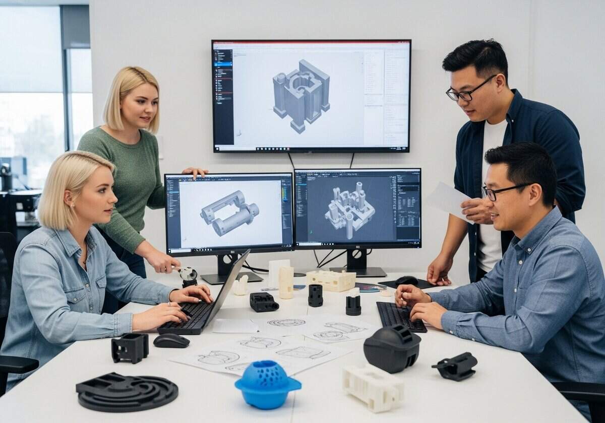
To Dive Deeper into Plastics

- Injection molding techniques: advanced methods for optimizing the injection molding process to improve efficiency and reduce defects.
- Material selection criteria: guidelines for selecting appropriate plastic materials based on mechanical properties, thermal resistance, and environmental impact
- Finite Element Analysis (FEA): simulation techniques to predict how plastic components will behave under various stresses and conditions
- Additive manufacturing (3D Printing): techniques for using 3D printing to create plastic prototypes and end-use parts, including material considerations
- Surface treatment methods: processes such as coating, painting, or texturing to enhance the appearance and functionality of plastic surfaces
- Thermoforming processes: techniques for shaping plastic sheets into specific forms using heat and pressure
- Blow molding Innovations: advanced methods in blow molding for creating hollow plastic parts with complex geometries
- Design for Manufacturability (DFM): principles that ensure plastic parts are designed in a way that simplifies manufacturing processes
- Sustainability in plastics: approaches to designing and engineering biodegradable or recycled plastics to reduce environmental impact
- Composite materials engineering: techniques for combining plastics with other materials (e.g., fibers) to enhance strength and performance
- Quality control techniques: methods for ensuring consistency and reliability in plastic products through statistical process control and testing
- Thermal management in...
You have read 82% of the article. The rest is for our community. Already a member? Log in
(and also to protect our original content from scraping bots)
Innovation.world community
Login or Register (100% free)
View the rest of this article and all members-only content and tools.
Only real engineers, manufacturers, designers, marketers professionals.
No bot, no hater, no spammer.


















What about the use of recycled materials?
Convinced how thoughtful design choices, like parting lines and overmolding, can lead to cost savings and enhanced functionality in plastic manufacturing.
It would be great to see more detailed examples of specific applications in future updates.
This article offers some overview of plastic design features in injection molding, highlighting the versatility and cost-effectiveness of the process.