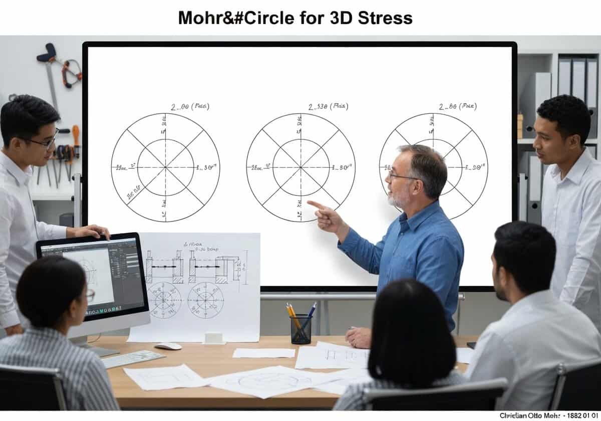
一般的な3次元状態の場合 ストレス解析結果は3つのモール円で表されます。これらの円は、3つの主応力(σ1、σ2、σ3)を直径として、σn τn 平面上に描かれます。σ1とσ3で定義される最大の円は、他の2つの円を囲み、絶対最大値を決定します。 せん断応力, [latex]tau_{abs max} = (sigma_1 – sigma_3)/2[/latex].

(画像はイメージです)
一般的な3次元状態の場合 ストレス解析結果は3つのモール円で表されます。これらの円は、3つの主応力(σ1、σ2、σ3)を直径として、σn τn 平面上に描かれます。σ1とσ3で定義される最大の円は、他の2つの円を囲み、絶対最大値を決定します。 せん断応力, [latex]tau_{abs max} = (sigma_1 – sigma_3)/2[/latex].
2次元のモール円は一般的ですが、実際の応力状態は3次元です。3次元の応力状態を解析するには、まず3つの主応力[latex]sigma_1 ge sigma_2 ge sigma_3[/latex]を決定します。これらは3次元の固有値です。 コーシー応力テンソルこれらの3つの値を使用して、3つの別々のモール円を作成します。最初の円は[latex]sigma_1[/latex]と[latex]sigma_2[/latex]の間に、2番目の円は[latex]sigma_2[/latex]と[latex]sigma_3[/latex]の間に、そして3番目の最大の円は[latex]sigma_1[/latex]と[latex]sigma_3[/latex]の間に描かれます。
The stress state ([latex]\sigma_n, \tau_n[/latex]) for any arbitrarily oriented plane at the point will lie within the shaded area bounded by these three circles. A crucial insight from this 3D representation is the determination of the absolute maximum せん断応力. Unlike the 2D case where the maximum in-plane shear is the radius, the absolute maximum shear stress for a 3D state is always the radius of the largest circle, given by [latex]\tau_{abs max} = R_{max} = (\sigma_{max} – \sigma_{min})/2 = (\sigma_1 – \sigma_3)/2[/latex]. This value is fundamental for applying failure criteria like the Tresca yield criterion in a general 3D context, as it represents the true maximum shear stress experienced by the material at that point.
3D応力に対するモール円
(日付が不明または関連性がない場合、例えば「流体力学」などでは、その注目すべき出現時期の概算値が提示されます。)
フルサイズの画像とダウンロードは、登録会員のみが100%無料で利用できます。
> ログイン <