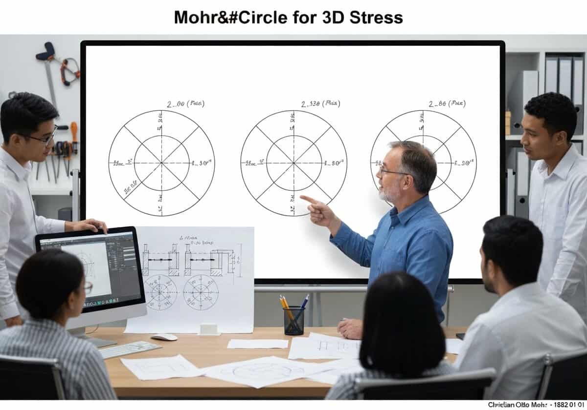
일반적인 3차원 상태의 경우 스트레스이 분석은 세 개의 모어 원으로 표현됩니다. 이 원들은 세 개의 주응력(σ₁, σ₂, σ₃)을 지름으로 사용하여 σₙ-τₙ 평면에 그려집니다. σ₁과 σ₃로 정의되는 가장 큰 원은 나머지 두 원을 모두 포함하며 절대 최댓값을 결정합니다. 전단 응력, [latex]tau_{abs max} = (sigma_1 – sigma_3)/2[/latex].

(설명을 위한 생성된 이미지입니다)
일반적인 3차원 상태의 경우 스트레스이 분석은 세 개의 모어 원으로 표현됩니다. 이 원들은 세 개의 주응력(σ₁, σ₂, σ₃)을 지름으로 사용하여 σₙ-τₙ 평면에 그려집니다. σ₁과 σ₃로 정의되는 가장 큰 원은 나머지 두 원을 모두 포함하며 절대 최댓값을 결정합니다. 전단 응력, [latex]tau_{abs max} = (sigma_1 – sigma_3)/2[/latex].
일반적으로 2차원 모어 원이 사용되지만, 실제 응력 상태는 3차원입니다. 3차원 응력 상태를 분석하려면 먼저 3차원 행렬의 고유값인 세 가지 주응력, 즉 [latex]sigma_1 ge sigma_2 ge sigma_3[/latex]을 구해야 합니다. 코시 응력 텐서이 세 값은 각각 세 개의 모어 원을 구성하는 데 사용됩니다. 첫 번째 원은 σ1과 σ2 사이에, 두 번째 원은 σ2와 σ3 사이에, 그리고 세 번째이자 가장 큰 원은 σ1과 σ3 사이에 그려집니다.
The stress state ([latex]\sigma_n, \tau_n[/latex]) for any arbitrarily oriented plane at the point will lie within the shaded area bounded by these three circles. A crucial insight from this 3D representation is the determination of the absolute maximum 전단 응력. Unlike the 2D case where the maximum in-plane shear is the radius, the absolute maximum shear stress for a 3D state is always the radius of the largest circle, given by [latex]\tau_{abs max} = R_{max} = (\sigma_{max} – \sigma_{min})/2 = (\sigma_1 – \sigma_3)/2[/latex]. This value is fundamental for applying failure criteria like the Tresca yield criterion in a general 3D context, as it represents the true maximum shear stress experienced by the material at that point.
Mohr’s Circle for 3D Stress
(날짜를 알 수 없거나 관련이 없는 경우, 예를 들어 "유체역학"의 경우, 주목할 만한 등장 시기를 대략적으로 추정하여 제공합니다.)
고화질 이미지 및 다운로드는 등록된 회원에게만 100% 무료로 제공됩니다.
> 로그인 <