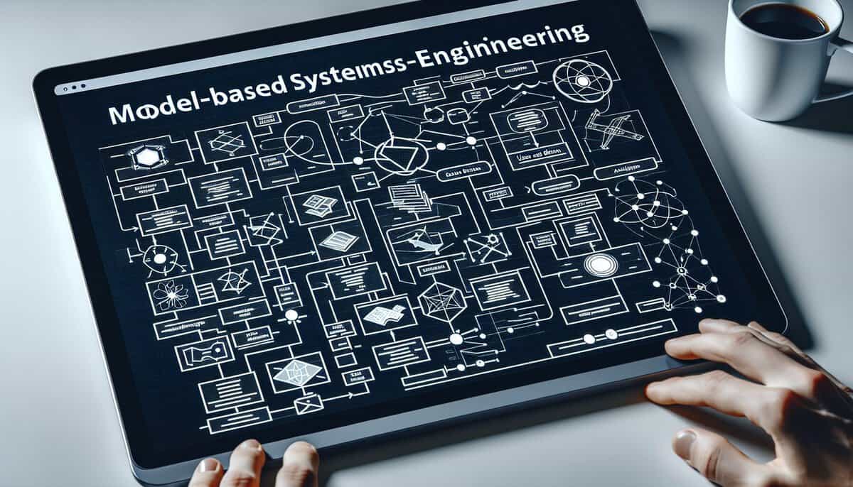
As industries evolve rapidly, the adoption of Model-Based Systems Engineering (MBSE) has surged, with studies indicating that organizations utilizing MBSE methodologies can reduce development time by as much as 30% (source: INCOSE). Central to this transformation is the Systems Modeling Language (SysML), a comprehensive modeling language designed to support the specification, analysis, design, and verification of complex systems. This article will dissect the nuances of SysML, from its diverse array of nine diagram types -including use case, block definition, and activity diagrams- to its critical language constructs like blocks, ports, and interfaces. By examining the benefits of SysML for system design and exploring essential tools and software for effective modeling, we aim to clarify its pivotal role in modern aerospace, automotive, and defense systems engineering. Furthermore, we will address the relationship between SysML and UML, enriching your understanding of these modeling tools within contemporary engineering practices.
Key Takeaways

- SysML supports structured representation of system requirements.
- Nine diagram types serve distinct modeling functions effectively.
- Key constructs facilitate robust system design and abstraction.
- Diverse tools exist for streamlined SysML model development.
- SysML extends UML capabilities to systems engineering domains.
Introduction to Model-Based Systems Engineering MBSE and the Role of SysML
Model-Based Systems Engineering (MBSE) represents a paradigm shift in systems engineering, moving from document-centric approaches to a model-centric approach. This evolution facilitates the creation, analysis, validation, and verification of system designs through the use of visual models rather than traditional text-based documentation. MBSE enhances communication among stakeholders by providing unified views of system components and their interdependencies, reducing ambiguities and improving the overall quality of engineering work. An illustrative statistic indicates that organizations adopting MBSE report a 50% reduction in time spent on documentation and a 30% improvement in collaboration efficiency.
Among the vital tools for implementing MBSE is the Systems Modeling Language (SysML).
SysML is designed specifically to address the needs of systems engineering by incorporating features for modeling requirements, behaviors, structures, and parametric relationships.
With a rich set of diagram types, SysML enables engineers to describe complex systems coherently. For example, a telemetry system designed for spacecraft can leverage SysML to portray interactions among subsystems, ranging from data acquisition to processing and transmission, visibly organizing all components and their functions.
In MBSE, SysML functions as a lingua franca, promoting better understanding across diverse engineering disciplines. The language’s blocks, ports, and interfaces serve as foundational constructs for representing system entities and their interactions. These elements collectively contribute to a robust framework that aids engineers in envisioning the entire system from multiple angles, improving design quality and traceability of requirements throughout the development lifecycle.
Integration of SysML with various engineering tools further optimizes MBSE practices. Specific software applications provide frameworks to model, simulate, and validate systems, allowing teams to identify issues early in the design process. Consequently, telecom companies have achieved substantial cost savings by correcting potential defects during early design phases rather than during later stages of production. A systematic approach that includes continuous validation and iteration can effectively reduce time-to-market by as much as 20%.
Overview of the 9 SysML Diagram Types and Their Purposes
The nine diagram types in SysML serve distinct purposes, contributing effectively to the modeling of complex systems:
- Block Definition Diagram (BDD) is primarily designed for showing system components and their relationships, providing a clear architecture overview.
- Internal Block Diagram (IBD) focuses on the internal structure of a block, illustrating how parts interact through ports and interfaces.
- Use Case Diagrams capture functional requirements, delineating the interactions between users (actors) and the system
- Sequence Diagrams model the time sequence of messages, clarifying temporal relationships during use case scenarios.
- State Machine Diagrams, the behavior of a system or its components can be represented as they transition between states based on events, which is critical in event-driven systems.
- Activity Diagrams, which describe the flow of control or data within the system
- Requirement Diagrams, outlining system requirements and their relationships
- Parametric Diagrams that model constraints, particularly in performance and design space
- Package Diagrams, which organize model elements into packages. Each diagram is tailored to enhance specific insights and facilitate communication among interdisciplinary teams.
Key SysML Language Constructs Including Blocks Ports and Interfaces
Blocks form the foundational elements of SysML, representing modular components that encapsulate both attributes and behaviors. A block can represent a physical component, a software module, or even a system itself. Each block can contain properties, which are defined using value types, relationships, and operations. This modular representation enhances reusability and simplifies system integration by allowing engineers to focus on smaller, manageable sections of the overall system. For example, in automotive design, a block might represent the engine, integrating performance metrics and fuel efficiency attributes that can be reused across different vehicle models.
Ports are specialized parts of blocks that enable interaction with external entities, be they other blocks or system components. These ports can be classified into various types, including standard, flow, and behavior ports, each serving a distinct purpose. Behavior ports allow a block to expose its operations, while flow ports facilitate the transmission of data or material. For instance, in aerospace applications, a block defining a satellite subsystem might utilize flow ports to manage data processed by sensors, ensuring effective data exchange and control.
Interfaces play a crucial role in defining the interactions between blocks through clearly specified contracts. They outline the required exchanges without delving into implementation specifics. By establishing interfaces, systems can align design and verification processes effectively. Statistical analyses have shown that organizations employing SysML interfaces can reduce design errors by up to 30% due to improved communication and clarity. This highlights the importance of properly defining interfaces in system designs to mitigate risks associated with integration failures.
Benefits of Using SysML for System Specification and Design
The integration of SysML into system specification and design significantly enhances clarity and communication among stakeholders across various phases of product development. By leveraging a structured approach, SysML enables the visualization of complex system interactions and dependencies. This increases team collaboration, reducing misunderstandings. For example, a study found that projects utilizing SysML reduced rework by 30% due to improved requirements traceability and stakeholder alignment.
Adopting SysML facilitates a unified framework for managing system requirements, architecture, and design. This model-based approach allows for efficient iteration and refinement of system components, promoting adaptability to changing requirements. Companies implementing SysML report a 20% average increase in development efficiency, attributed to the reduction of manual documentation and streamlined communication.
The use of SysML also enhances verification and validation processes through rigorous modeling of system behaviors...
You have read 57% of the article. The rest is for our community. Already a member? Log in
(and also to protect our original content from scraping bots)
Innovation.world community
Login or Register (100% free)
View the rest of this article and all members-only content and tools.
Only real engineers, manufacturers, designers, marketers professionals.
No bot, no hater, no spammer.
Related Readings
- Integration of SysML with Agile Methodologies: sysML can be adapted within agile frameworks to enhance iterative development processes.
- SysML for Requirements Traceability: utilizing sysML diagrams to track and manage requirements throughout the system lifecycle.
- Model Verification and Validation Techniques: methods to ensure models meet specified requirements and operate as intended.
- SysML in Safety Analysis: application of sysML models for assessing and improving system safety and reliability.
- Interfacing SysML with Hardware-in-the-Loop Testing: integrating sysML models with physical systems for real-time testing.
- SysML for Model-Based Systems of Systems Engineering: addressing challenges and methodologies for systems that interact as larger integrated solutions.
- SysML and Digital Twin Development: using sysML to create digital twins that mirror and simulate real-world systems.
- Automation and Scripting in SysML Tools: leveraging automation capabilities in sysML modeling tools to improve efficiency and consistency.
External Links on Systems Modeling Language (SysML)
International Standards
(hover the link to see our description of the content)
Glossary of Terms Used
Model-Based Systems Engineering (MBSE): a methodology that uses models to support the specification, design, analysis, verification, and validation of complex systems, enhancing communication and understanding among stakeholders throughout the system lifecycle. It emphasizes the use of visual representations and formal modeling techniques.
Systems Modeling Language (SysML): a general-purpose modeling language designed for systems engineering, enabling the specification, analysis, design, verification, and validation of complex systems. It supports various modeling perspectives, including requirements, behavior, structure, and parametric relationships, facilitating communication among stakeholders.
Unified Modeling Language (UML): a standardized modeling language used in software engineering to visualize, specify, construct, and document software system artifacts through various diagram types, including class, use case, sequence, and activity diagrams. It facilitates communication among stakeholders and supports object-oriented design.
Verification and Validation (V&V): a process to ensure a system meets specifications and fulfills its intended purpose, involving two distinct activities: verification checks if the product meets design specifications, while validation assesses if it satisfies user needs and requirements.


