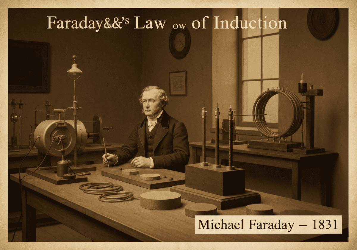
Faraday’s Law of Induction (integral form)
This law states that the electromotive force (EMF, \(\mathcal{E}\)) induced in any closed circuit is equal to the negative of the time rate of change of the magnetic flux (\(\Phi_B\)) through the circuit. The mathematical expression is \(\mathcal{E} = -\frac{d\Phi_B}{dt}\). This principle is the basis for electric generators, transformers, and inductors, describing the macroscopic effect of induction.
The integral form of Faraday’s law of induction provides a macroscopic view of the relationship between a changing magnetic environment and an electrical circuit. It defines the electromotive force, or EMF (\(\mathcal{E}\)), as the line integral of the electric field \(\mathbf{E}\) around a closed loop \(\partial\Sigma\): \(\mathcal{E} = \oint_{\partial\Sigma} \mathbf{E} \cdot d\mathbf{l}\). This EMF represents the total voltage that would be measured by a voltmeter placed in the loop if it were cut open. The law equates this EMF to the rate of change of magnetic flux, \(\Phi_B\), passing through the surface \(\Sigma\) bounded by the loop.
Magnetic flux is defined as the surface integral of the magnetic field \(\mathbf{B}\) over the surface \(\Sigma\): \(\Phi_B = \iint_\Sigma \mathbf{B} \cdot d\mathbf{A}\). Therefore, the full law is written as \(\oint_{\partial\Sigma} \mathbf{E} \cdot d\mathbf{l} = -\frac{d}{dt} \iint_\Sigma \mathbf{B} \cdot d\mathbf{A}\). The negative sign, formalized by Lenz’s law, indicates that the induced EMF creates a current that generates a magnetic field opposing the original change in flux. This opposition is a manifestation of the conservation of energy.
This law is remarkably general. The change in flux can be caused by several factors: the magnetic field itself can change in strength, the loop can change its area, the orientation of the loop relative to the field can change, or any combination of these. This versatility explains its application in a vast range of devices. For instance, in an AC generator, a coil of wire (the loop) is rotated in a constant magnetic field, continuously changing the orientation and thus the flux, inducing a sinusoidal EMF. In a transformer, a changing current in a primary coil creates a changing magnetic field, which in turn induces an EMF in a secondary coil.
UNESCO Nomenclature: 2205
– Electromagnetism
Precursors
- Discovery of the magnetic properties of lodestone
- William Gilbert’s work on magnetism (‘De Magnete’, 1600)
- Hans Christian Ørsted’s observation that electric currents create magnetic fields (1820)
- André-Marie Ampère’s mathematical description of electromagnetism
Applications
- electric transformers
- alternating current (AC) generators
- induction motors
- inductors in electronic circuits
- credit card magnetic stripe readers
- electric guitar pickups
- ground fault circuit interrupters (GFCIs)
Potential Innovations Ideas
Due to scrapping bot traffic, currently more than 40k per day, this content is reserved to community members.
> Login < or > Register < (100% free) to access this, so as all other restricted content and tools.
Related to: faraday’s law, integral form, electromotive force, magnetic flux, induction, lenz’s law, electric generator, transformer.