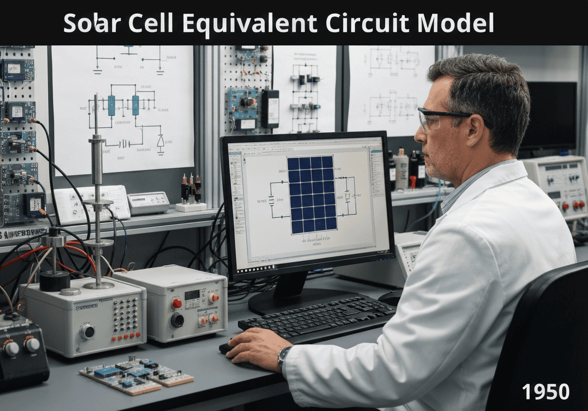
A solar cell can be modeled by an equivalent electrical circuit. The simplest model includes a current source representing the photogenerated current ([latex]I_L[/latex]), in parallel with a diode representing the p-n junction. A more accurate model adds a parallel shunt resistance ([latex]R_{sh}[/latex]) for leakage currents and a series resistance ([latex]R_s[/latex]) for contact and bulk material resistance.
Solar Cell Equivalent Circuit Model
The equivalent circuit model is a powerful tool for understanding and analyzing the electrical behavior of a solar cell. It abstracts the complex semiconductor physics into a simple circuit diagram with a few key components. The core of the model is an ideal current source that produces a current, [latex]I_L[/latex], directly proportional to the incident light intensity. This represents the generation of electron-hole pairs by photons.
In parallel with this current source is a diode. This diode models the behavior of the p-n junction itself. In the dark, the solar cell is just a diode, and its current-voltage (I-V) characteristic follows the ideal diode equation. When illuminated, some of the photogenerated current is shunted through this internal diode, a process known as recombination, which does not contribute to the output current. The total output current [latex]I[/latex] is therefore the photogenerated current minus the diode current: [latex]I = I_L – I_D[/latex].
For a more realistic representation, two parasitic resistances are added. A series resistance, [latex]R_s[/latex], accounts for the resistance of the metal contacts, the emitter, and the bulk semiconductor material. It causes a voltage drop that reduces the terminal voltage and the fill factor. A shunt resistance, [latex]R_{sh}[/latex], is placed in parallel with the diode and current source. It represents leakage paths for the current across the p-n junction, often due to Herstellung defects. A low shunt resistance provides an alternate path for the photogenerated current, reducing the current delivered to the load. The governing equation for this single-diode model is: [latex]I = I_L – I_0 \left[ \exp\left(\frac{V+IR_s}{n k_B T/q}\right) – 1 \right] – \frac{V+IR_s}{R_{sh}}[/latex], where [latex]I_0[/latex] is the diode saturation current and [latex]n[/latex] is the ideality factor.
Typ
Disruption
Verwendung
Precursors
- development of diode theory (shockley diode equation)
- ohm’s law
- kirchhoff’s circuit laws
- invention of the p-n junction solar cell
Anwendungen
- predicting solar cell performance under varying conditions
- characterizing solar panels in manufacturing (i-v curve tracing)
- designing maximum power point tracking (mppt) algorithms
- simulating the behavior of large photovoltaic arrays
Patente:
Potential Innovations Ideas
!Professionals (100% free) Mitgliedschaft erforderlich
Sie müssen ein Professionals (100% free) Mitglied sein, um auf diesen Inhalt zugreifen zu können.
VERFÜGBAR FÜR NEUE HERAUSFORDERUNGEN
Maschinenbauingenieur, Projekt- oder F&E-Manager
Kurzfristig für eine neue Herausforderung verfügbar.
Kontaktieren Sie mich auf LinkedIn
Integration von Kunststoff-Metall-Elektronik, Design-to-Cost, GMP, Ergonomie, Geräte und Verbrauchsmaterialien in mittleren bis hohen Stückzahlen, regulierte Branchen, CE und FDA, CAD, Solidworks, Lean Sigma Black Belt, medizinische ISO 13485
Wir suchen einen neuen Sponsor
Ihr Unternehmen oder Ihre Institution beschäftigt sich mit Technik, Wissenschaft oder Forschung?
> Senden Sie uns eine Nachricht <
Erhalten Sie alle neuen Artikel
Kostenlos, kein Spam, E-Mail wird nicht verteilt oder weiterverkauft
oder Sie können eine kostenlose Vollmitgliedschaft erwerben, um auf alle eingeschränkten Inhalte zuzugreifen >Hier<
Historical Context
Solar Cell Equivalent Circuit Model
(if date is unknown or not relevant, e.g. "fluid mechanics", a rounded estimation of its notable emergence is provided)
Related Invention, Innovation & Technical Principles