HomeProduct DesignTechnologiesMust-know PCB and Electronic Components Vocabulary

Must-know PCB and Electronic Components Vocabulary

To know for product design: mastered by electronics engineers, these basic electronic components vocabulary, PCB technologies, and most used components footprints are a must-know also for product designers, mechanical designers, project managers, and regulatory engineers for project development efficiency.

Basic Electronic Components Types

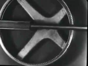
  • Resistors: a passive two-terminal electrical component that resists the flow of current.
  • Capacitors: a passive two-terminal electrical component that stores electrical energy in an electric field.
  • Inductors: a passive two-terminal electrical component that stores energy in a magnetic field.
  • Diodes: a two-terminal electronic component that allows current to flow in one direction only.
  • Transistors: a three-terminal electronic component that can be used to amplify or switch electrical signals. When assembled in billions, transistors are the base of all modern computing logic.
  • Relays: an electrically operated switch that can be used to control a variety of electrical circuits.
    Through-hole resistors, the most basic electronic component
    Through-hole resistors, the most basic electronic component
  • Optoelectronics: electronic components that convert light into electrical signals or vice versa. LED (Light Emitting Diode) is one of them.
  • Oscillators: electronic components that generate an alternating current at a specific frequency.
  • Voltage Regulators: an electronic group of components that maintain a constant voltage output.
  • Transformers: electronic components that can be used to change the voltage or current of an electrical signal.
  • Crystals: electronic components that are used to control the frequency of an oscillator circuit.
  • Filters: an electronic group of components that are used to remove unwanted frequencies from an electrical signal.
  • Integrated Circuits (ICs): a set of interconnected electronic components, as the ones described above, usually on a single semiconductor chip, that can perform a variety of functions.
PCB vocabulary
PCB vocabulary

The PCB Vocabulary

  • PCB: (Printed Circuit Board) is the base support used to create electronic circuits. It is a board made of insulating material, such as fiberglass, with conductive pathways etched into it.
  • PCBA: stands for Printed Circuit Board Assembly, which is the process of soldering components onto the PCB to create a functioning electronic circuit. This includes mounting components, such as integrated circuits, resistors, and capacitors, onto the board and soldering them in place.
  • Solder Mask: the thin layer of polymer applied to the surface of a printed circuit board (PCB) to protect the copper traces from oxidation and shorting.
  • Platin: the process used to coat a metal surface with a thin layer of another metal, such as tin or gold.
  • Etching: as described above, the process of removing unwanted material from a PCB by using a chemical solution.
  • Lamination: the process of bonding two or more layers of material together to form a single unit.
  • Copper Clad Laminate: the material used to construct a PCB, consisting of a thin layer of copper foil bonded to a substrate.
  • Silkscreen: as in printing, the A process used to print text and graphics onto a PCB.
Electronic Circuit Traces
  • Circuit Trace: the thin copper line on a PCB used to connect electrical components.
  • Via: a small hole in a PCB, filled with soldering, used to connect two or more layers through the board.
  • SMT (Surface Mount Technology): the method of mounting electronic components onto a PCB using solder paste and a reflow oven without drilling the PCB. Specific components are described hereafter.
  • Through-hole: as the opposite of the SMT above, the through-hole type is the assembly process where components are mounted onto the printed circuit board and soldered in place by passing their leads or pins through holes in the PCB and then soldering them on the opposite side. This method of assembly is also known as through-hole mounting, pin-in-hole mounting, or hole-through mounting.
  • BGA (Ball Grid Array): an array of solder balls used to connect a component to a PCB
  • Wave Soldering: the process used to solder components to a PCB using a wave of molten solder.
  • Reflow Oven: an oven used to heat a PCB and melt the solder paste, allowing components to be soldered to the board.
  • Panelization: the process of arranging multiple PCBs on a single panel for efficient manufacturing.
  • Routing: the process of cutting away excess material from a PCB using a router
  • Test Fixture or Tester: the device used to test the functionality of a PCB.
  • Gerber File: the file format used to describe the layout of components, traces, and layers of the PCB.
  • Pick and Place: an automatic computer-controlled machine used to place components onto a PCB at high speed.
  • Automated Optical Inspection (AOI): a machine used to inspect a PCB for defects.

Electronic Components Shapes & Footprints

Through-hole Electronic Components

Through-hole Electronic Components

  • Axial Lead: this is the most common type of through-hole footprint, consisting of two leads extending from the sides of the component body.
  • Radial Lead: this type of footprint consists of two or more leads extending from the sides of the component body in a circular pattern.
  • DIP (Dual In-line Package): this integrated circuit package has a rectangular shape and two rows of pins extending on each side
  • SIP (Single In-line Package): similar to the DIP above but with only one line: this type of footprint consists of one row of leads extending from the sides of the electronic component body.

Standardized Through-hole Shapes

Among many other shapes, these are for some transistors:

Footprint or Shape NameSurface Mount Standardized ShapeExamples
TO-126, TO-92, TO-39, TO-18, TO-5 …

a three-lead package with or without a metal can, to be used for small-signal transistors.

TO-126 electronic component package
TO-92 electronic component package
TO-3, TO-3P, TO-220, TO-220F, TO-247 …a three-lead package with a metal tab for heat sinkinIog and an additional fixture, to be used for power transistors.
TO-220 electronic component package

Surface Mount Electronic Components

Surface Mount Components
  • SOIC (Small Outline Integrated Circuit): This is a type of integrated circuit package with a rectangular shape and a row of pins on each side.
  • QFP (Quad Flat Package): this type of footprint consists of four rows of leads extending from each side of the component body in a rectangular pattern.
  • PLCC (Plastic Leaded Chip Carrier): this type of footprint consists of two rows of leads extending from the sides of the component body in a rectangular pattern.
  • PGA (Pin Grid Array): this type of footprint consists of a grid of pins on the underside of the component body. Contrary to the BGA described here-after, it requires a socket to be mounted, and as such is not exactly a surface mount component.
  • QFN (Quad Flat No-Lead): this type of footprint consists of four rows of leads extending from the sides of the electronic component body in a rectangular pattern, but without any leads extending from the bottom of the component body.
  • PLCC (Plastic Leaded Chip Carrier): This is a type of integrated circuit package with a square shape and a row of pins on each side.

  • BGA (Ball Grid Array): this type of footprint consists of a grid of solder balls on the underside of the component body.

  • SOT (Small Outline Transistor): This is a type of transistor package with a rectangular shape and a row of pins on each side.

Standardized Surface Mount Footprints Sizes

TI 16-pin package footprint comparison
TI 16-pin package footprint comparison (copyright Texas Instruments)

Some of the most used:

Footprint NameSurface Mount Standardized Footprint SizeTypical application
“0201”0.6mm x 0.3mm

These are used for small passive components such as resistors and capacitors.

Due to the small size, only an automatic pick-and-place assembly is possible here.

“0402”0.6mm x 0.4mm
“0603”0.6mm x 0.5mm 
“0805”0.8mm x 0.5mm
“1206”1.2mm x 0.6mm
SOT-232.9mm x 1.3mmThese are typically used for large active components such as transistors and diodes.
SOT-2234.9mm x 3.1mm
SOT-896.1mm x 3.1mm
SOT-5537.9mm x 5.3mm


Read more on electronic components and their applications on Wikipedia’s Electronic Portal or at the Institute of Electrical and Electronics Engineers (IEEE).

RELATED ARTICLES
Exact matches only
include Online Tools
include Events

WIKI / PARTICIPATE !

Share suggestions, corrections,  examples, experience or ideas that may be integrated in this article

In English, if Monday is the first day of the week, by which letter starts the third day? (correct answer is needed to be able to submit)

NEW / UPDATED

The 7 Habits of Highly Effective People animated slideshow

"7 Habits of Highly Effective People" made famous by Stephen R. Covey is powerfully summarized in seven(!) minutes,...

The 14 Lean Principles of The Toyota Way

To resume many of the lean principles of a company or attitude, one book is key. From the...

The 5 Japanese Lean Terms You Must Know in Manufacturing and Quality

For Manufacturing: the Japanese Lean terms are must-know vocabulary in manufacturing or quality as these have no direct...

3 Great Benefits of Color Coding in Product Design

Product designers and marketers can use color coding for 3 reasons: to convey a message, to convey a...

Best 40 TRIZ Principles to Boost Your Design Challenges

For product design engineers. The 40 TRIZ Principles are the solutions to solve the "TRIZ contradictions" in product...

UPCOMING EVENTS