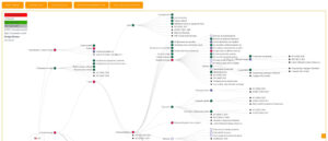
The Scoping Diagram serves as an integral tool in various stages of product design and engineering, particularly during the initial phases of project definition and requirement gathering, where clarity of scope is paramount. It finds applications across industries such as automotive, aerospace, consumer electronics, and healthcare, where complex systems and multiple stakeholders are involved. By visually mapping out the relationships between the central process or system and its external elements, stakeholders can easily identify essential interfaces, dependencies, and the boundaries of the project. Engaging participants such as project managers, engineers, designers, and even end-users in this visualization activity can facilitate a collaborative environment, fostering a shared understanding of the project’s focus. This method proves valuable during workshops or brainstorming sessions aimed at framing project objectives or analyzing process performance, allowing teams to clarify expectations and potentially identify areas for innovation. The visual representation aids in differentiating between what will be included in the scope and what will be explicitly excluded, thus preventing scope creep later in development. Clarity in defining these boundaries accelerates decision-making processes and helps teams avoid miscommunications that may arise during subsequent project phases.