
Gli strumenti di intelligenza artificiale online stanno rapidamente trasformando l'ingegneria meccanica, aumentando le capacità umane di progettazione, analisi, produzione e manutenzione. Questi sistemi di intelligenza artificiale sono in grado di elaborare grandi quantità di dati, identificare modelli complessi e generare soluzioni innovative molto più rapidamente dei metodi tradizionali. Ad esempio, l'IA può aiutarvi a ottimizzare i progetti in termini di prestazioni e producibilità, accelerare simulazioni complesse, prevedere le proprietà dei materiali e automatizzare un'ampia gamma di attività analitiche.
I suggerimenti forniti qui di seguito aiuteranno, ad esempio, a progettare in modo generativo, ad accelerare le simulazioni (FEA/CFD), ad aiutare nella manutenzione predittiva, dove l'intelligenza artificiale analizza i dati dei sensori dei macchinari per prevedere potenziali guasti, consentendo un'assistenza proattiva e riducendo al minimo i tempi di inattività, ad aiutare nella selezione dei materiali e molto altro ancora.
Progettazione concettuale e brainstorming
[prompt_formatter title=”Generazione di concetti di meccanismi innovativi” description=”Propone vari concetti meccanici per ottenere un movimento o un compito specifico, ampliando lo spazio di soluzioni a disposizione dell'ingegnere. Descrive in dettaglio i principi di funzionamento, i vantaggi e gli svantaggi di ciascun meccanismo proposto.” temperature=”0.8” thinking=”high"]## DESCRIZIONE DEL COMPITO⸻Generare concetti meccanici innovativi per ottenere il movimento o l'attività specificati. Fornire principi di funzionamento dettagliati, vantaggi e svantaggi per ciascun concetto.⸻⸻## INPUT⸻1. **Movimento o attività specifici**: il movimento o l'attività che il meccanismo deve realizzare:{specific_motion_or_task}.⸻2. **Vincoli e requisiti**: i vincoli o i requisiti che devono essere considerati: {constraints_and_requirements}.⸻⸻## OUTPUT⸻1. **Elenco di concetti**: generare un elenco di almeno tre concetti meccanici innovativi.⸻2. **Principi di funzionamento**: per ciascun concetto, descrivere in dettaglio i principi di funzionamento.⸻3. **Vantaggi e svantaggi**: fornire un elenco completo dei vantaggi e degli svantaggi di ciascun concetto.⸻⸻## ISTRUZIONI⸻1. Analizzare il movimento o l'attività specificati e i relativi vincoli.⸻2. Generare una serie diversificata di concetti meccanici che potrebbero realizzare il movimento o l'attività.⸻3. Per ciascun concetto, descrivere in dettaglio i principi di funzionamento, evidenziando come realizza il movimento o l'attività.⸻4. Elenca i vantaggi e gli svantaggi, considerando fattori quali efficienza, complessità, costo e affidabilità.⸻5. Assicurati che i concetti siano innovativi e ampliano lo spazio di soluzione oltre gli approcci convenzionali.⸻⸻## NOTE⸻- Concentrati sulla creatività e sulla fattibilità.⸻- Considera approcci interdisciplinari, se applicabile.⸻- Se necessario, utilizza diagrammi o schizzi per illustrare concetti complessi.[/prompt_formatter]
[prompt_formatter title=”Biomimetica per la progettazione ingegneristica” description=”Identifica i sistemi biologici che hanno risolto un problema ingegneristico simile, fornendo ispirazione dalla natura per progetti innovativi. Spiega il meccanismo naturale e come può essere adattato per un'applicazione tecnica.” temperature=”0.7” thinking=”high"]## PANORAMICA DEL COMPITO⸻Identifica i sistemi biologici che hanno affrontato efficacemente sfide ingegneristiche simili a {your_engineering_problem}. Fornisci approfondimenti su come funzionano questi meccanismi naturali e proponi adattamenti per applicazioni tecniche.⸻⸻## REQUISITI DI INPUT⸻1. Definire il problema ingegneristico specifico: {your_engineering_problem}.⸻2. Specificare eventuali vincoli o requisiti per la soluzione: {constraints_and_requirements}.⸻⸻## STRUTTURA DI OUTPUT⸻1. **Identificazione dei sistemi biologici**⸻ – Identificare e descrivere i sistemi biologici che hanno risolto problemi simili.⸻ – Spiegare i meccanismi naturali coinvolti.⸻⸻2. **Analisi dei meccanismi**⸻ – Analizzare l'efficienza e l'efficacia di questi meccanismi.⸻ – Discutere le condizioni ambientali in cui operano.⸻⸻3. **Proposta di adattamento**⸻ – Proporre come questi meccanismi naturali possano essere adattati alla sfida ingegneristica fornita come input.⸻ – Suggerire potenziali materiali, strutture o processi ispirati a questi sistemi.⸻⸻4. **Valutazione di fattibilità**⸻ – Valutare la fattibilità dell'implementazione degli adattamenti proposti.⸻ – Considerare i fattori tecnici, economici e ambientali.⸻⸻## ISTRUZIONI AGGIUNTIVE⸻- Utilizzare terminologia scientifica e fornire riferimenti a studi o ricerche biologiche pertinenti.⸻- Garantire chiarezza e precisione nella spiegazione dei meccanismi e degli adattamenti.⸻- Evidenziare gli aspetti innovativi delle soluzioni proposte.[/prompt_formatter]
[prompt_formatter title=”Schema della specifica di progettazione del prodotto (PDS)” description=”Genera un modello completo per un documento di specifica di progettazione del prodotto (PDS). Questo assicura che tutti i requisiti chiave, come le metriche delle prestazioni, i vincoli dei materiali e gli standard di sicurezza, siano definiti all'inizio di un progetto.” temperature=”0.3″ thinking=”medium”]# GENERAZIONE DEL TEMPLATE OUTLINE DELLA SPECIFICA DI PROGETTAZIONE DEL PRODOTTO (PDS)⸻⸻## OBIETTIVO⸻Generare un template dettagliato della specifica di progettazione del prodotto (PDS) per definire tutti i requisiti chiave del progetto, compresi i parametri di prestazione, i vincoli dei materiali e gli standard di sicurezza.⸻⸻## ISTRUZIONI⸻1. **COMPRENSIONE DEL PROGETTO**⸻ - Fornire una breve descrizione del progetto, compreso lo scopo e l'ambito di applicazione.⸻ - Definire il mercato di riferimento e le esigenze degli utenti.⸻⸻2. **METRICHE DI PRESTAZIONE**⸻ - Elencare tutte le metriche di prestazione critiche che il prodotto deve raggiungere.⸻ - Includere obiettivi quantitativi e metodi di misurazione.⸻⸻3. **CONSIGLIAZIONI MATERIALI**⸻ - Specificare eventuali requisiti o restrizioni sui materiali.⸻ - Considerare fattori quali la durata, il costo e l'impatto ambientale.⸻⸻4. **Norme di sicurezza**⸻ - Identificare le norme e i regolamenti di sicurezza pertinenti.⸻ - Delineare i requisiti di conformità e le procedure di test.⸻⸻5. **REQUISITI FUNZIONALI**⸻ - Descrivere in dettaglio le funzioni essenziali che il prodotto deve svolgere.⸻ - Includere user interface E usabilità considerazioni.⸻⸻6. **Considerazioni ambientali**⸻ - Affrontare l'impatto ambientale e gli obiettivi di sostenibilità.⸻ - Includere l'analisi del ciclo di vita e i piani di smaltimento a fine vita.⸻⸻7. **Costi e vincoli di bilancio**⸻ - Definire i limiti di bilancio e gli obiettivi di costo.⸻ - Considerare i costi di produzione, manutenzione e funzionamento.⸻⸻8. **TIMELINE E MILESTONES**⸻ - Stabilire una timeline del progetto con le tappe fondamentali.⸻ - Includere le scadenze per ogni fase del progetto.⸻⸻## FORMATO DI USCITA⸻ Fornire il modello di PDS in un formato strutturato, pronto per la personalizzazione con dettagli specifici del progetto.⸻⸻## USER INPUT⸻Sostituire i segnaposto con le informazioni specifiche del progetto, ove applicabile.⸻⸻## NOTE AGGIUNTIVE⸻Assicurarsi che il modello sia adattabile a vari tipi di prodotti e industrie.[/prompt_formatter]
[prompt_formatter title=”Brainstorming sull'architettura di sistema” description=”Elabora diverse architetture di sistema di alto livello per un prodotto complesso con sottosistemi dati, mostrando diversi modi di organizzare i sottosistemi. Se necessario, genera diagrammi in formato Mermaid. Questo aiuta a confrontare fin dall'inizio i compromessi tra filosofie di progettazione modulari, integrate e di altro tipo.” temperature=”0.7” thinking=”high“]**PANORAMICA DEL COMPITO**⸻Generare architetture di sistema di alto livello per un prodotto complesso utilizzando i sottosistemi forniti. Esplorare varie disposizioni per confrontare i compromessi tra filosofie di progettazione modulari, integrate e di altro tipo. Utilizzare il formato Mermaid per la generazione di diagrammi, se necessario.⸻⸻**REQUISITI DI INPUT**⸻1. Elenco dei sottosistemi: {list_of_subsystems}⸻2. Filosofie di progettazione da esplorare: {design_philosophies}⸻3. Vincoli o requisiti specifici: {constraints_requirements}⸻⸻**OUTPUT**⸻1. Architetture di sistema multiple di alto livello che mostrano diverse disposizioni dei sottosistemi dati.⸻2. Diagrammi in formato Mermaid per ciascuna architettura, se applicabile.⸻3. Analisi dei compromessi per ciascuna filosofia di progettazione, concentrandosi su modularità, integrazione e altre filosofie specificate.⸻⸻**PROCESSO**⸻1. Analizzare l'elenco dei sottosistemi e identificare potenziali interazioni e dipendenze.⸻2. Per ciascuna filosofia di progettazione, creare un'architettura di alto livello che organizzi i sottosistemi di conseguenza.⸻3. Generare diagrammi in formato Mermaid per rappresentare visivamente ciascuna architettura.⸻4. Valutare i compromessi di ciascuna architettura, considerando fattori quali scalabilità, flessibilità, complessità e prestazioni.⸻5. Riassumere i risultati ed evidenziare le differenze chiave tra le architetture.⸻⸻**MODELLO DI DIAGRAMMA MERMAID**⸻“`mermaid⸻graph TD⸻A[Sottosistema A] –> B[Sottosistema B]⸻B –> C[Sottosistema C]⸻“`⸻⸻**NOTE AGGIUNTIVE**⸻Assicurarsi che tutte le architetture rispettino i vincoli e i requisiti specificati. Regolare il livello di dettaglio dei diagrammi in base alla complessità del sistema e alle esigenze dell'analisi.[/prompt_formatter]
[prompt_formatter title=”Brainstorming Solutions for a Design Flaw” description=”Generates a list of creative and practical solutions to address a specific, identified design flaw. This accelerates the problem-solving process by providing a wide range of potential fixes.” temperature=”0.8″ thinking=”high”]**TASK OVERVIEW**⸻Identify and address a specific design flaw by generating a comprehensive list of creative and practical solutions.⸻⸻**INPUT REQUIREMENTS**⸻1. Description of the design flaw: {design_flaw_description}⸻2. Context of the design (e.g., product type, usage environment): {design_context}⸻3. Constraints and requirements (e.g., cost, materials, time): {design_constraints}⸻⸻**OUTPUT EXPECTATIONS**⸻Generate a list of potential solutions that are both creative and practical. Each solution should include:⸻- A brief description of the solution⸻- Potential benefits⸻- Possible drawbacks⸻- Implementation feasibility⸻⸻**PROCESS**⸻1. Analyze the provided design flaw and context.⸻2. Consider the constraints and requirements.⸻3. Brainstorm a diverse range of solutions, ensuring a balance between creativity and practicality.⸻4. Evaluate each solution based on feasibility, benefits, and drawbacks.⸻5. Compile the solutions into a structured list with detailed descriptions.⸻⸻**OUTPUT FORMAT**⸻- Solution 1:⸻ – Description: $solution1_description⸻ – Benefits: $solution1_benefits⸻ – Drawbacks: $solution1_drawbacks⸻ – Feasibility: $solution1_feasibility⸻- Solution 2:⸻ – Description: $solution2_description⸻ – Benefits: $solution2_benefits⸻ – Drawbacks: $solution2_drawbacks⸻ – Feasibility: $solution2_feasibility⸻- … (continue for additional solutions)⸻⸻**ADDITIONAL NOTES**⸻Ensure that the solutions are innovative yet grounded in practical application. Consider cross-disciplinary approaches and emerging technologies where applicable.[/prompt_formatter]
Selezione dei materiali e dei componenti
[prompt_formatter title=”Selezione dei materiali per ambienti estremi” description=”Suggerisce e confronta i materiali per un componente che opera in condizioni estreme specifiche (ad esempio, alta temperatura, corrosione, alta pressione). L'output fornisce un elenco classificato di materiali con proprietà chiave e giustificazioni.” temperature=”0,7″ thinking=”high”]## SELEZIONE DEI MATERIALI PER AMBIENTI ESTREMI⸻⸻### INPUT REQUISITI⸻- Definire le condizioni estreme specifiche che il componente dovrà affrontare: {extreme_conditions} (ad esempio, alta temperatura, corrosione, alta pressione).⸻- Specificare eventuali vincoli o requisiti aggiuntivi: (ad esempio, limiti di peso, considerazioni sui costi).⸻⸻### TASK⸻1. Analizzare le condizioni estreme e i vincoli dati.⸻2. Identificare i potenziali materiali adatti a queste condizioni.⸻3. Confrontare i materiali in base a proprietà chiave come la resistenza termica, resistenza alla corrosione, mechanical strength, and cost.⸻4. Rank the materials from most to least suitable for the specified conditions.⸻5. Provide justifications for the ranking, highlighting the advantages and disadvantages of each material.⸻⸻### OUTPUT⸻- A ranked list of materials with key properties and justifications for each.⸻- Include a summary of the analysis and recommendations for the best material choice.⸻⸻### EXAMPLE⸻- Input: {extreme_conditions} = “high temperature, corrosive”; {additional_constraints} = “low cost”⸻- Output:⸻ 1. Material A: High thermal resistance, excellent corrosion resistance, moderate cost. Justification: Best balance of properties for the specified conditions.⸻ 2. Material B: Moderate thermal resistance, good corrosion resistance, low cost. Justification: Suitable for budget constraints but less effective at high temperatures.⸻ 3. Material C: Excellent thermal resistance, moderate corrosion resistance, high cost. Justification: Superior performance but not cost-effective.⸻⸻### ADDITIONAL NOTES⸻- Ensure the analysis considers the latest material science research and industry standards.⸻- Use reliable data sources and references for material properties and performance.[/prompt_formatter]
[prompt_formatter title=”Sustainable Material Alternatives” description=”Proposes environmentally friendly and sustainable material alternatives for a given application. It includes data on recyclability, embodied energy, and lifecycle impact to support green design choices.” temperature=”0.7″ thinking=”medium”]**TASK OVERVIEW**⸻Identify sustainable material alternatives for a specific application, focusing on recyclability, embodied energy, and lifecycle impact.⸻⸻**INPUT REQUIREMENTS**⸻1. Define the application context: {application_context}.⸻2. Specify any current materials used: {current_materials}.⸻3. List any specific sustainability criteria or constraints: {sustainability_criteria}.⸻⸻**PROCESS**⸻1. Analyze the {application_context} to understand the functional requirements of the material.⸻2. Evaluate the {current_materials} for their environmental impact, focusing on recyclability, embodied energy, and lifecycle impact.⸻3. Research alternative materials that meet the {sustainability_criteria} and functional requirements.⸻4. Compare the alternatives based on:⸻⸻ a. Recyclability: Assess the ease and efficiency of riciclaggio processes.⸻ b. Embodied Energy: Calculate the total energy consumed during production.⸻ c. Lifecycle Impact: Evaluate the environmental impact throughout the material’s lifecycle.⸻⸻5. Propose the most suitable sustainable material alternatives, providing detailed data and justification for each choice.⸻⸻**OUTPUT**⸻Provide a comprehensive report detailing:⸻1. The analysis of the current materials.⸻2. The proposed sustainable alternatives.⸻3. Data on recyclability, embodied energy, and lifecycle impact for each alternative.⸻4. A comparative analysis justifying the recommended materials for {application_context}.⸻⸻**ADDITIONAL NOTES**⸻Ensure all data sources are credible and up-to-date. Include references where applicable.[/prompt_formatter]
[prompt_formatter title=”Off-the-Shelf Component Sourcing” description=”Identifies standard, off-the-shelf components (e.g., bearings, elementi di fissaggio, motors) that meet a specific set of technical requirements. This saves time and cost compared to designing custom parts.” temperature=”0.7″ thinking=”medium”]**TASK**⸻Identify and select standard off-the-shelf components that meet the specified technical requirements.⸻⸻**INPUT REQUIREMENTS**⸻1. Define the technical specifications and constraints for the component: {component_type}, {load_capacity}, {dimensions}, {material}, {operating_conditions}, {certifications}.⸻2. Provide any additional preferences or constraints: {preferred_brands}, {budget_limits}, {lead_time_constraints}.⸻⸻**PROCESS**⸻1. Search for available off-the-shelf components that match the defined specifications and constraints.⸻2. Evaluate the components based on compatibility with the specified requirements and additional preferences.⸻3. List potential suppliers and compare their offerings based on cost, availability, and compliance with the technical requirements.⸻4. Recommend the top components and suppliers that best meet the criteria.⸻⸻**OUTPUT**⸻Provide a detailed report including:⸻- A list of identified components with specifications.⸻- Supplier information and contact details.⸻- Comparison of components based on cost, availability, and compliance.⸻- Final recommendation with justification.⸻⸻**NOTES**⸻Ensure all data is up-to-date and verify supplier credibility before finalizing the recommendation.[/prompt_formatter]
Design for Manufacturing and Assembly (DFM/DFA)
[prompt_formatter title=”DFM/DFA Checklist Generation” description=”Creates a customized checklist for Design for Manufacturing and Assembly based on specified production processes (e.g., CNC machining, injection molding, sheet metal). This helps optimize designs for efficient and cost-effective production.” temperature=”0.3″ thinking=”medium”]**TASK**⸻Generate a customized Design for Manufacturing and Assembly (DFM/DFA) checklist.⸻⸻**INPUT REQUIREMENTS**⸻1. Specify the production process: {production_process} (e.g., CNC machining, injection molding, sheet metal).⸻2. List any specific design constraints or requirements: {design_constraints}.⸻3. Provide any relevant industry standards or guidelines: {industry_standards}.⸻⸻**OUTPUT**⸻Provide a detailed DFM/DFA checklist tailored to the specified production process, including:⸻- Key design considerations for {production_process}.⸻- Potential cost-saving opportunities.⸻- Common pitfalls and how to avoid them.⸻- Recommendations for improving manufacturability and assembly efficiency.⸻⸻**ADDITIONAL INSTRUCTIONS**⸻Ensure the checklist is comprehensive and considers all aspects of the specified production process.⸻Reference the provided {design_constraints} and {industry_standards} where applicable.⸻Focus on optimizing designs for both efficiency and cost-effectiveness.[/prompt_formatter]
[prompt_formatter title=”Tolerance Stack-up Analysis Guidance” description=”Outlines the steps, tips and best practices for performing a tolerance stack-up analysis on a mechanical assembly of a given type, process or industry. This provides a structured method to ensure components fit and function correctly.” temperature=”0.3″ thinking=”medium”]# TOLERANCE STACK-UP ANALYSIS GUIDANCE⸻⸻## INPUT REQUIREMENTS⸻- Specify the type of mechanical assembly: {assembly_type}⸻- Define the industry or process context: {industry_or_process}⸻- Provide component specifications and tolerances: {component_specifications}⸻- List any known constraints or critical dimensions: {constraints_or_critical_dimensions}⸻⸻## ANALYSIS STEPS⸻1. **Component Identification**⸻ – List all components involved in the assembly.⸻ – Identify each component’s role and interaction within the assembly.⸻2. **Tolerance Data Collection**⸻ – Gather all relevant tolerance data for each component.⸻ – Ensure data accuracy and relevance to {industry_or_process}.⸻3. **Assembly Path Definition**⸻ – Define the assembly path and sequence.⸻ – Identify key interfaces and mating surfaces.⸻4. **Tolerance Stack-up Calculation**⸻ – Use worst-case, statistical, or Monte Carlo methods as applicable.⸻ – Calculate cumulative tolerances for the assembly.⸻5. **Analysis and Optimization**⸻ – Identify potential fit or function issues.⸻ – Propose adjustments or redesigns to optimize tolerance distribution.⸻6. **Documentation and Reporting**⸻ – Document the analysis process and results.⸻ – Prepare a report summarizing findings and recommendations.⸻⸻## BEST PRACTICES⸻- Use consistent units and measurement standards.⸻- Validate assumptions with empirical data or simulations.⸻- Collaborate with cross-functional squadre for comprehensive insights.⸻- Regularly review and update tolerance data as designs evolve.[/prompt_formatter]
[prompt_formatter title=”Jigs and Fixtures Design Concepts” description=”Brainstorms different design concepts for jigs and fixtures needed to manufacture or assemble a specific component. This improves the efficiency, repeatability, and safety of production processes.” temperature=”0.7″ thinking=”medium”]# JIGS AND FIXTURES DESIGN CONCEPTS⸻⸻## OBJECTIVE⸻Generate innovative design concepts for jigs and fixtures to enhance the efficiency, repeatability, and safety of manufacturing or assembling {specific_component}.⸻⸻## INPUT REQUIREMENTS⸻1. Component Details: Provide detailed specifications, dimensions, and any unique features of {specific_component}.⸻2. Manufacturing/Assembly Process: Describe the current process or intended process for manufacturing or assembling {specific_component}.⸻3. Constraints: List any constraints such as material limitations, space restrictions, or budget considerations.⸻4. Safety Requirements: Specify any safety standards or considerations that must be adhered to.⸻⸻## OUTPUT EXPECTATIONS⸻1. Conceptual Designs: Generate at least three distinct design concepts for jigs and fixtures.⸻2. Efficiency Analysis: Provide a brief analysis of how each design concept improves efficiency.⸻3. Repeatability Assessment: Evaluate the potential for each design to enhance process repeatability.⸻4. Safety Evaluation: Assess the safety features and compliance of each design concept.⸻⸻## INSTRUCTIONS⸻1. Analyze the provided component details and process description to understand the specific needs.⸻2. Consider the constraints and safety requirements when generating design concepts.⸻3. Use creativity and engineering principles to brainstorm innovative solutions.⸻4. Document each design concept with sketches or diagrams if possible.⸻⸻## ADDITIONAL CONSIDERATIONS⸻- Explore the use of advanced materials or technologies that could enhance the design.⸻- Consider modularity and adaptability for future component variations.⸻- Evaluate the cost-effectiveness of each design concept.⸻⸻## FINAL OUTPUT⸻Provide a comprehensive report summarizing the design concepts, analyses, and evaluations.[/prompt_formatter]
[prompt_formatter title=”Post-Processing for Additive Manufacturing” description=”Details the necessary post-processing steps and rough time estimation for a 3D-printed part based on the chosen printing technology, specific material, and requirements.” temperature=”0.5″ thinking=”medium”]**TASK OVERVIEW**⸻Provide a detailed plan for post-processing a 3D-printed part.⸻Include necessary steps and time estimates based on the chosen printing technology, material, and specific requirements.⸻⸻**INPUT REQUIREMENTS**⸻1. Printing Technology: {FDM/SLA/SLS/other}⸻2. Material Type: {material_name}⸻3. Part Requirements: {requirements_description}⸻4. Part Complexity: {simple/medium/complex}⸻5. Surface Finish Quality: {standard/high}⸻6. Dimensional Tolerance: {tolerance_value}⸻⸻**OUTPUT EXPECTATIONS**⸻1. List of Post-Processing Steps:⸻- Describe each step in detail.⸻- Specify tools and materials needed.⸻2. Time Estimation:⸻- Provide rough time estimates for each step.⸻- Include total time estimation.⸻3. Additional Recommendations:⸻- Suggest improvements or alternatives if applicable.⸻- Highlight any potential challenges.⸻⸻**CONSTRAINTS**⸻- Ensure compatibility with the specified printing technology and material.⸻- Align with the given part requirements and quality standards.⸻- Consider efficiency and cost-effectiveness.⸻⸻**EXECUTION**⸻Analyze the input data to tailor the post-processing plan.⸻Use industry standards and best practices to inform recommendations.⸻Provide a concise and actionable output.[/prompt_formatter]
Simulation and Analysis
[prompt_formatter title=”Finite Element Analysis (FEA) Sanity Check” description=”Provides a list of common mistakes and critical checks to perform before and after running a Elemento finito Analysis of a given part or industry. This helps ensure the accuracy and reliability of the simulation results.” temperature=”0.3″ thinking=”medium”]# FEA SANITY CHECK⸻⸻## INPUT REQUIREMENTS⸻- Part or Industry Description: {part_or_industry_description}⸻- Material Properties: {material_properties}⸻- Boundary Conditions: {boundary_conditions}⸻- Load Cases: {load_cases}⸻- Mesh Details: {mesh_details}⸻⸻## PRE-FEA CHECKS⸻1. **Geometry Verification**: Ensure the geometry is clean and free of defects such as gaps or overlaps.⸻2. **Material Properties**: Verify that the material properties are accurate and relevant to the part or industry.⸻3. **Boundary Conditions**: Check that all boundary conditions are correctly applied and reflect real-world constraints.⸻4. **Load Cases**: Confirm that all load cases are defined correctly and are representative of actual operating conditions.⸻5. **Mesh Quality**: Evaluate the mesh for quality, ensuring it is sufficiently refined in critical areas.⸻⸻## POST-FEA CHECKS⸻1. **Convergence Check**: Verify that the solution has converged by checking residuals and other convergence criteria.⸻2. **Result Validation**: Compare simulation results with known benchmarks or experimental data to validate accuracy.⸻3. **Stress and Strain Distribution**: Analyze stress and strain distributions for unexpected concentrations or anomalies.⸻4. **Deformation Patterns**: Review deformation patterns to ensure they are physically plausible.⸻5. **Sensitivity Analysis**: Conduct sensitivity analysis to understand the impact of varying parameters on results.⸻⸻## COMMON MISTAKES⸻- Incorrect application of boundary conditions.⸻- Over-simplification of the model leading to inaccurate results.⸻- Ignoring mesh quality, resulting in poor accuracy.⸻- Misinterpretation of results due to lack of validation.⸻⸻## OUTPUT⸻Provide a summary of the checks performed and any identified issues or recommendations for improvement.⸻⸻## EXECUTION⸻Use the input data to perform the checks and provide a detailed report on the findings, ensuring all critical aspects are covered.[/prompt_formatter]
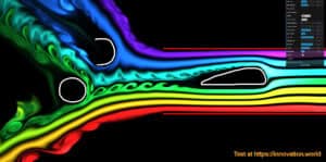
[prompt_formatter title=”CFD Boundary Condition Recommendations” description=”Suggests appropriate boundary conditions for a Computational Fluid Dynamics (CFD) analysis of a specific scenario (e.g., airflow over a heat sink). This is crucial for setting up an accurate and realistic simulation.” temperature=”0.7″ thinking=”high”]**TASK**⸻Provide expert-level recommendations for setting up boundary conditions in a Computational Fluid Dynamics (CFD) simulation for the specified scenario.⸻⸻**INPUT REQUIREMENTS**⸻1. Describe the specific CFD scenario: {scenario_description}.⸻2. Specify the fluid properties: {fluid_properties}.⸻3. Define the geometry and domain of the simulation: {geometry_and_domain}.⸻4. Identify any specific physical phenomena to be captured: {physical_phenomena}.⸻5. Note any constraints or assumptions: {constraints_assumptions}.⸻⸻**OUTPUT**⸻1. List the recommended boundary conditions for the given scenario.⸻2. Provide a rationale for each recommended boundary condition.⸻3. Suggest any additional considerations or adjustments for achieving realistic simulation results.⸻⸻**CONSIDERATIONS**⸻- Ensure that the boundary conditions align with the physical phenomena and constraints specified.⸻- Consider the impact of boundary conditions on the stability and accuracy of the simulation.⸻- Address potential challenges in implementing the boundary conditions within the specified geometry and domain.⸻⸻**FORMAT**⸻- Use bullet points for clarity.⸻- Separate each recommendation and rationale clearly.⸻- Include references to any relevant literature or best practices if applicable.[/prompt_formatter]
[prompt_formatter title=”Fatigue Life Prediction Checklist” description=”Outlines the key steps, data inputs, and analysis models required to perform a fatigue life prediction of a given type or scenario. This guides engineers in assessing the durability of components subjected to cyclic loading.” temperature=”0.3″ thinking=”medium”]## FATIGUE LIFE PREDICTION CHECKLIST⸻⸻### OBJECTIVE⸻Provide a comprehensive checklist for predicting the fatigue life of components subjected to cyclic loading. This includes identifying key steps, necessary data inputs, and suitable analysis models.⸻⸻### INPUT REQUIREMENTS⸻1. **Component Details**: Describe the component, including material properties, geometry, and surface finish.⸻2. **Loading Conditions**: Specify the type of cyclic loading (e.g., tension-compression, bending, torsion) and loading spectrum.⸻3. **Environmental Factors**: Note any environmental conditions affecting the component (e.g., temperature, corrosion).⸻4. **Historical Data**: Provide any available fatigue test data or historical performance data.⸻⸻### CHECKLIST STEPS⸻1. **Material Characterization**:⸻- Gather material properties such as Young’s modulus, limite di snervamento, ultimate tensile strength, and fatigue limit.⸻- Identify any material treatments or coatings.⸻⸻2. **Load Analysis**:⸻
– Determine the stress range and mean stress for the loading conditions.⸻- Calculate stress concentration factors if applicable.⸻⸻3. **Fatigue Analysis Model Selection**:⸻- Choose an appropriate fatigue life prediction model (e.g., S-N curve, strain-life approach, fracture mechanics).⸻- Justify the selection based on component characteristics and loading conditions.⸻⸻4. **Data Input Preparation**:⸻- Prepare input data for the chosen model, ensuring accuracy and completeness.⸻- Consider any necessary data transformations or normalizations.⸻⸻5. **Simulation and Analysis**:⸻- Perform fatigue life simulations using the selected model and input data.⸻- Analyze results to identify potential failure points and life expectancy.⸻⸻6. **Validation and Verification**:⸻- Compare simulation results with historical data or experimental results for validation.⸻
– Adjust model parameters if discrepancies are found.⸻⸻7. **Documentation and Reporting**:⸻- Document the analysis process, assumptions, and results.⸻- Prepare a comprehensive report detailing the fatigue life prediction and recommendations.⸻⸻### OUTPUT⸻- A detailed checklist and report summarizing the fatigue life prediction, including identified failure points, life expectancy, and recommendations for design improvements or further testing.⸻⸻### ADDITIONAL NOTES⸻- Ensure all data inputs are accurate and reflect real-world conditions as closely as possible.⸻- Consider the use of software tools for complex simulations and data analysis.⸻⸻### END OF CHECKLIST⸻[/prompt_formatter]
[prompt_formatter title=”Thermal Management Strategy Brainstorming” description=”Proposes various active and passive cooling strategies for a system that generates heat of a given type. It compares methods like heat sinks, heat pipes, and forced convection to find the optimal solution.” temperature=”0.7″ thinking=”high”]**TASK**⸻Analyze and propose optimal thermal management strategies for a system that generates heat.⸻⸻**INPUT REQUIREMENTS**⸻1. Specify the type of heat generated by the system: {heat_type}.⸻2. Provide system specifications including dimensions, material properties, and operating conditions: {system_specifications}.⸻3. List any constraints or requirements for the cooling solution (e.g., size, weight, cost): {constraints}.⸻⸻**ANALYSIS**⸻1. Evaluate the effectiveness of passive cooling methods:⸻ – Heat sinks: Consider material, fin design, and surface area.⸻ – Heat pipes: Assess thermal conductivity and integration feasibility.⸻2. Evaluate the effectiveness of active cooling methods:⸻ – Forced convection: Analyze fan or blower options, airflow requirements, and power consumption.⸻ – Liquid cooling: Consider pompa capacity, coolant type, and heat exchanger efficiency.⸻⸻**COMPARISON**⸻1. Compare the proposed methods based on efficiency, cost, and feasibility.⸻2. Identify trade-offs and potential integration challenges.⸻⸻**OUTPUT**⸻Provide a detailed comparison and recommendation for the optimal thermal management strategy, including:⸻1. A summary of the proposed methods and their evaluations.⸻2. A recommended solution with justification based on the analysis.⸻⸻**ADDITIONAL CONSIDERATIONS**⸻- Suggest any innovative or emerging technologies that could be applicable.⸻- Discuss potential environmental impacts and sustainability of the proposed solutions.[/prompt_formatter]
CAD, GD&T, and Documentation
[prompt_formatter title=”GD&T Callout Recommendations” description=”Suggests appropriate Geometric Dimensioning and Tolerancing (GD&T) callouts for a part based on its function and mating interfaces. This ensures the design intent is clearly communicated for manufacturing and inspection” temperature=”0.5″ thinking=”medium”]**TASK OVERVIEW**⸻Analyze the part’s function and mating interfaces to recommend suitable GD&T callouts.⸻⸻**INPUT REQUIREMENTS**⸻1. Part Description: Provide a detailed description of the part, including its primary function and any critical features.⸻2. Mating Interfaces: Describe the interfaces where the part connects with other components, including any specific alignment or fit requirements.⸻3. Tolerancing Priorities: List any specific tolerancing priorities or constraints that must be considered.⸻⸻**OUTPUT**⸻1. Recommended GD&T Callouts: A list of GD&T callouts that align with the part’s function and mating interfaces.⸻2. Justification: A brief explanation for each recommended callout, detailing how it supports the design intent and manufacturing requirements.⸻⸻**PROCESS**⸻1. Analyze the provided part description and identify key functional features.⸻2. Evaluate the mating interfaces to determine necessary alignment and fit requirements.⸻3. Cross-reference tolerancing priorities with GD&T principles to ensure compliance.⸻4. Generate a list of GD&T callouts with justifications for each.⸻⸻**ADDITIONAL NOTES**⸻Ensure that all recommendations are compliant with the latest GD&T standards and best practices.⸻Consider any industry-specific requirements that may influence tolerancing decisions.[/prompt_formatter]
[prompt_formatter title=”Bill of Materials (BOM) Template” description=”Creates a structured Bill of Materials (BOM) template with standard and custom fields (to be provided) for a mechanical assembly specific to a provided industry. This helps in organizing parts, managing procurement, and estimating costs.” temperature=”0.3″ thinking=”medium”]**TASK**⸻Create a structured Bill of Materials (BOM) template for a mechanical assembly.⸻⸻**INPUT REQUIREMENTS**⸻1. Industry Type: {industry_type}⸻2. Standard Fields: {list_of_standard_fields}⸻3. Custom Fields: {list_of_custom_fields}⸻⸻**INSTRUCTIONS**⸻1. Analyze the provided {industry_type} to determine relevant components and materials typically used.⸻2. Compile a list of standard fields from {list_of_standard_fields} that are essential for a BOM in this industry.⸻3. Integrate {list_of_custom_fields} to address specific needs or requirements unique to the mechanical assembly.⸻4. Structure the BOM template to include sections for part numbers, descriptions, quantities, units of measure, and any additional fields specified.⸻5. Ensure the template facilitates easy updates and modifications for procurement and cost estimation purposes.⸻⸻**OUTPUT**⸻Provide a structured BOM template with the following sections:⸻- Header: Industry Type, Date, Project Name⸻- Body: Standard Fields, Custom Fields⸻- Footer: Notes, Revision History⸻⸻**FORMAT**⸻Use a tabular format for the BOM template with clear headings for each section and field.⸻⸻**ADDITIONAL NOTES**⸻Ensure the template is adaptable for future modifications and scalable for different project sizes.[/prompt_formatter]
[prompt_formatter title=”Technical Report Structure Template” description=”Generates a standard template for a formal engineering report specific to a provided industry. This provides a logical structure with all necessary sections, such as an introduction, methodology, results, and conclusion recommended in that industry.” temperature=”0.3″ thinking=”medium”]**TASK**⸻Generate a standard template for a formal engineering report specific to the {industry}.⸻⸻**INPUT REQUIREMENTS**⸻1. Industry: {industry}⸻2. Specific focus or topic of the report: {report_topic}⸻⸻**OUTPUT STRUCTURE**⸻1. **Title Page**⸻⸻2. **Abstract**⸻⸻3. **Table of Contents**⸻⸻4. **Introduction**⸻- Context and background of {report_topic} in {industry}⸻- Objectives of the report⸻⸻5. **Literature Review**⸻- Summary of existing research and developments in {industry} related to {report_topic}⸻⸻6. **Methodology**⸻- Detailed description of methods and processes used in the study⸻- Justification for chosen methods⸻⸻7. **Results**⸻- Presentation of data and findings⸻- Use of tables, graphs, and charts as necessary⸻⸻8. **Discussion**⸻- Interpretation of results⸻- Comparison with existing literature⸻- Implications for {industry}⸻⸻9. **Conclusion**⸻- Summary of key findings⸻- Recommendations for future work or applications⸻⸻10. **References**⸻- List of all sources cited in the report⸻⸻11. **Appendices**⸻- Additional material supporting the report⸻⸻**INSTRUCTIONS**⸻1. Customize each section with specific details relevant to {report_topic} and {industry}.⸻2. Ensure all sections are logically connected and comprehensive.⸻3. Follow industry standards for formatting and citation.[/prompt_formatter]
[prompt_formatter title=”Technical Standard Summary” description=”Summarizes a lengthy and complex technical standard into a concise overview, highlighting key requirements and implications for a specific given design.” temperature=”0.5″ thinking=”medium”]**TASK OVERVIEW**⸻Summarize a complex technical standard document, focusing on key requirements and implications for a specific design.⸻⸻**INPUT REQUIREMENTS**⸻1. Provide the full text or a link to the technical standard document: {technical_standard_document}⸻2. Specify the design or project context for which the summary is needed: {design_context}⸻⸻**PROCESS**⸻1. Analyze the provided technical standard document to identify sections relevant to the specified design context.⸻2. Extract key requirements, guidelines, and constraints that directly impact the design.⸻3. Identify any critical compliance or regulatory implications.⸻4. Summarize the findings into a concise overview, emphasizing the most important points for the design.⸻⸻**OUTPUT FORMAT**⸻- **Key Requirements**: $key_requirements⸻- **Design Implications**: $design_implications⸻- **Compliance Considerations**: $compliance_considerations⸻⸻**ADDITIONAL NOTES**⸻Ensure the summary is clear and directly applicable to the specified design context, avoiding unnecessary details that do not impact the design.⸻Use bullet points or numbered lists for clarity where appropriate.[/prompt_formatter]
System Integration and Safety
[prompt_formatter title=”Component Integration Checklist” description=”Generates a checklist for a given set of elements to ensure proper mechanical, electrical, and software integration between different subsystems.” temperature=”0.7″ thinking=”medium”]# COMPONENT INTEGRATION CHECKLIST GENERATOR⸻⸻## INPUT REQUIREMENTS⸻- List of subsystems involved: {list_of_subsystems}⸻- Mechanical components and interfaces: {mechanical_components}⸻- Electrical components and interfaces: {electrical_components}⸻- Software components and interfaces: {software_components}⸻- Integration standards or protocols: {integration_standards}⸻⸻## TASK⸻Generate a comprehensive checklist to ensure seamless integration of mechanical, electrical, and software components across the specified subsystems.⸻⸻## OUTPUT FORMAT⸻1. **Mechanical Integration**⸻ – Verify mechanical compatibility between {mechanical_components} across {list_of_subsystems}.⸻ – Ensure alignment and fit of mechanical interfaces.⸻ – Check for compliance with {integration_standards}.⸻⸻2. **Electrical Integration**⸻ – Confirm electrical connectivity and compatibility between {electrical_components}.⸻ – Validate power requirements and distribution across {list_of_subsystems}.⸻ – Ensure adherence to {integration_standards}.⸻⸻3. **Software Integration**⸻ – Assess software compatibility and communication protocols between {software_components}.⸻ – Verify data exchange and synchronization across {list_of_subsystems}.⸻ – Ensure software interfaces comply with {integration_standards}.⸻⸻4. **General Integration Checks**⸻ – Conduct a system-wide test to identify potential interface issues.⸻ – Document and resolve any discrepancies found during integration.⸻ – Review and update the checklist based on integration outcomes.⸻⸻## EXECUTION⸻Use the provided input to generate the checklist, ensuring all aspects of mechanical, electrical, and software integration are covered comprehensively.[/prompt_formatter]
[prompt_formatter title=”Failure Mode and Effects Analysis (Analisi FMEA) Starter” description=”Generates a preliminary FMEA table for a given mechanical system. This systematically identifies potential failure modes, their effects, and possible causes early in the design process.” temperature=”0.3″ thinking=”medium”]**TASK OVERVIEW**⸻Generate a preliminary FMEA table for a mechanical system to identify potential failure modes, their effects, and possible causes.⸻⸻**INPUT REQUIREMENTS**⸻1. Define the mechanical system: {mechanical_system_description}.⸻2. List key components: {list_of_components}.⸻3. Specify operating conditions: {operating_conditions}.⸻4. Identify known issues or historical failures: {known_issues}.⸻⸻**PROCESS**⸻1. Analyze each component in {list_of_components} to identify potential failure modes.⸻2. For each failure mode, determine the possible effects on the system and its operation.⸻3. Identify potential causes for each failure mode based on {operating_conditions} and {known_issues}.⸻4. Prioritize failure modes based on severity, occurrence, and detection likelihood.⸻⸻**OUTPUT FORMAT**⸻Generate a table with the following columns:⸻- Component⸻- Failure Mode⸻- Effect of Failure⸻- Cause of Failure⸻- Severity⸻- Occurrence⸻- Detection⸻- Numero di priorità del rischio (RPN)⸻⸻**ADDITIONAL INSTRUCTIONS**⸻- Use industry standards for severity, occurrence, and detection ratings.⸻- Provide a summary of the top three critical failure modes with the highest RPN.⸻- Suggest mitigation strategies for the top critical failure modes.⸻⸻**END OF TASK**[/prompt_formatter]
[prompt_formatter title=”Risk Assessment Matrix” description=”Creates a valutazione del rischio matrix (likelihood vs. severity) and populates it with potential hazards for a given mechanical system in a given industry and the number of desired steps. This provides a structured way to identify and prioritize safety risks.” temperature=”0.7″ thinking=”medium”]# RISK ASSESSMENT MATRIX CREATION⸻⸻## INPUT REQUIREMENTS⸻1. Define the mechanical system: {mechanical_system_description}⸻2. Specify the industry: {industry_type}⸻3. Determine the number of steps for the assessment: {number_of_steps}⸻⸻## TASK EXECUTION⸻1. **Identify Potential Hazards**⸻- List potential hazards associated with {mechanical_system_description} in {industry_type}.⸻2. **Assess Likelihood and Severity**⸻- For each hazard, evaluate the likelihood of occurrence and potential severity of impact.⸻3. **Create Risk Assessment Matrix**⸻- Construct a matrix with likelihood on one axis and severity on the other.⸻- Populate the matrix with identified hazards, categorizing them based on their likelihood and severity.⸻4. **Prioritize Risks**⸻- Rank the hazards in order of priority based on their position in the matrix.⸻5. **Develop Mitigation Strategies**⸻- Suggest strategies to mitigate high-priority risks.⸻⸻## OUTPUT⸻- Provide a structured risk assessment matrix with prioritized hazards and suggested mitigation strategies.⸻- Output format: $risk_assessment_matrix⸻⸻## ADDITIONAL INSTRUCTIONS⸻- Ensure clarity and precision in hazard identification and risk prioritization.⸻- Use industry-specific knowledge to enhance the accuracy of the assessment.[/prompt_formatter]
[prompt_formatter title=”Test Plan Outline for a Physical Prototype” description=”Generates a comprehensive test plan for validating a given physical prototype in a given industry and its main manufacturing process used. The output includes key performance indicators to measure, test procedures, required equipment, and data collection methods.” temperature=”0.7″ thinking=”high”]**TASK**⸻Generate a comprehensive test plan for validating a physical prototype.⸻⸻**INPUT REQUIREMENTS**⸻1. Industry: {industry_name}⸻2. Prototype Description: {prototype_description}⸻3. Main Manufacturing Process: {manufacturing_process}⸻⸻**OUTPUT**⸻Provide a detailed test plan including:⸻⸻1. **Key Performance Indicators (KPIs):**⸻- List the KPIs relevant to the prototype and industry.⸻- Explain why each KPI is critical for validation.⸻⸻2. **Test Procedures:**⸻- Outline step-by-step procedures for each test.⸻- Include conditions and parameters for testing.⸻⸻3. **Required Equipment:**⸻- List all necessary equipment and tools.⸻- Specify any special calibration or setup needed.⸻⸻4. **Data Collection Methods:**⸻- Describe methods for collecting and recording data.⸻- Include data analysis techniques to be used.⸻⸻**CONSIDERATIONS**⸻- Ensure alignment with industry standards and regulations.⸻- Address any safety and environmental concerns.⸻⸻**FORMAT**⸻Present the test plan in a structured format for easy reference and implementation.[/prompt_formatter]
Problem Solving and Troubleshooting
[prompt_formatter title=”Root Cause Analysis of Mechanical Failure” description=”Creates a fishbone (Ishikawa) diagram draft in Mermaid format populated with potential root causes for a specific mechanical failure. This provides a structured framework for effective troubleshooting and further investigations.” temperature=”0.5″ thinking=”medium”]**TASK**⸻Generate a fishbone (Ishikawa) diagram draft in Mermaid format to identify potential root causes for a specific mechanical failure.⸻⸻**INPUT REQUIREMENTS**⸻1. Specify the mechanical failure to be analyzed: {mechanical_failure_description}.⸻2. List the main categories of potential causes (e.g., Materials, Methods, Machines, Measurements, Environment, People): {cause_categories}.⸻3. Provide any known specific potential causes under each category: {specific_causes}.⸻⸻**OUTPUT FORMAT**⸻Generate the fishbone diagram in Mermaid format as follows:⸻“`mermaid⸻graph LR⸻A[Mechanical Failure: {mechanical_failure_description}] –> B1[{cause_category_1}]⸻A –> B2[{cause_category_2}]⸻A –> B3[{cause_category_3}]⸻…⸻B1 –> C1[{specific_cause_1}]⸻B1 –> C2[{specific_cause_2}]⸻B2 –> D1[{specific_cause_3}]⸻…⸻“`⸻⸻**INSTRUCTIONS**⸻1. Replace {mechanical_failure_description} with the specific mechanical failure being analyzed.⸻2. Replace {cause_categories} with the main categories of potential causes.⸻3. Replace {specific_causes} with any known specific potential causes under each category.⸻4. Ensure the diagram is logically structured and comprehensive for effective troubleshooting.⸻⸻**ADDITIONAL NOTES**⸻- The diagram should serve as a draft for further investigation and refinement.⸻- Consider consulting with team members or experts to validate and expand upon the potential causes listed.[/prompt_formatter]
[prompt_formatter title=”Vibration Troubleshooting Guide” description=”Creates a step-by-step guide for diagnosing and mitigating excessive vibration in a given specific machine. It covers potential sources like imbalance, misalignment, and resonance, along with common solutions for that machine.” temperature=”0.7″ thinking=”high”]# VIBRATION TROUBLESHOOTING GUIDE⸻⸻## INPUT REQUIREMENTS⸻1. Machine Type: {machine_type}⸻2. Machine Specifications: {machine_specifications}⸻3. Observed Vibration Symptoms: {vibration_symptoms}⸻4. Operating Conditions: {operating_conditions}⸻⸻## DIAGNOSTIC STEPS⸻1. **Initial Assessment**⸻ – Gather machine history and maintenance records.⸻ – Identify recent changes in operation or environment.⸻⸻2. **Vibration Analysis**⸻ – Measure vibration levels using appropriate sensors.⸻ – Compare with standard vibration thresholds for {machine_type}.⸻⸻3. **Identify Potential Sources**⸻ – Check for imbalance: Inspect rotating components for uneven mass distribution.⸻ – Check for misalignment: Verify alignment of shafts and couplings.⸻ – Check for resonance: Identify natural frequencies and compare with operating frequencies.⸻⸻## MITIGATION STRATEGIES⸻1. **Imbalance Solutions**⸻ – Perform dynamic balancing of rotating parts.⸻ – Replace or repair damaged components.⸻⸻2. **Misalignment Solutions**⸻ – Realign shafts and couplings using laser alignment tools.⸻ – Ensure proper installation procedures are followed.⸻⸻3. **Resonance Solutions**⸻ – Modify structural supports to alter natural frequencies.⸻ – Adjust operating speed to avoid resonance zones.⸻⸻## FINAL CHECKS⸻1. Re-measure vibration levels post-mitigation.⸻2. Compare with initial measurements to confirm reduction.⸻3. Document all findings and actions taken for future reference.⸻⸻## OUTPUT⸻- Provide a detailed report summarizing the diagnostic process and solutions implemented.⸻- Include recommendations for ongoing monitoring and maintenance.⸻[/prompt_formatter]
Project Management and Communication
[prompt_formatter title=”Project Timeline and Milestone Suggestions” description=”Creates a high-level project timeline with key milestones for a typical mechanical design project of a given industry. This assists in project planning, resource allocation, and progress tracking.” temperature=”0.7″ thinking=”medium”]**TASK**⸻Generate a high-level project timeline with key milestones for a mechanical design project in the {industry} industry.⸻⸻**INPUT REQUIREMENTS**⸻1. Industry: Specify the industry for the mechanical design project, e.g., automotive, aerospace, consumer electronics.⸻2. Project Duration: Define the total expected duration of the project in weeks or months.⸻3. Key Phases: List the key phases of the project, such as concept development, design, prototyping, testing, and production.⸻4. Milestone Criteria: Define criteria for key milestones, such as design approval, prototype completion, testing results, and production readiness.⸻⸻**OUTPUT**⸻1. A detailed project timeline with start and end dates for each phase.⸻2. Key milestones with estimated completion dates and criteria.⸻3. Suggestions for resource allocation and potential bottlenecks.⸻⸻**INSTRUCTIONS**⸻1. Analyze the provided industry and project duration to tailor the timeline.⸻2. Break down the project into specified phases and allocate time based on industry standards.⸻3. Identify key milestones within each phase and suggest realistic completion dates.⸻4. Provide recommendations for resource allocation and highlight potential bottlenecks or risks.⸻⸻**EXAMPLE**⸻Industry: Automotive⸻Project Duration: 12 months⸻Key Phases: Concept Development, Design, Prototyping, Testing, Production⸻Milestone Criteria: Design Approval, Prototype Completion, Testing Results, Production Readiness⸻⸻**OUTPUT FORMAT**⸻- Project Timeline: $projecttimeline⸻- Key Milestones: $keymilestones⸻- Resource Allocation Suggestions: $resourceallocation⸻- Potential Bottlenecks: $potentialbottlenecks[/prompt_formatter]
[prompt_formatter title=”Stakeholder Communication Plan” description=”Develops a communication plan for an engineering project with a given industry and specific challenges, identifying key stakeholders, their interests, and the appropriate communication methods. This ensures information flows effectively throughout the project lifecycle.” temperature=”0.7″ thinking=”medium”]# STAKEHOLDER COMMUNICATION PLAN⸻⸻## INPUT REQUIREMENTS⸻- **Industry**: Specify the industry related to the engineering project (e.g., automotive, aerospace, construction).⸻- **Project Challenges**: Describe the specific challenges faced in the project.⸻- **Project Lifecycle Stages**: List the stages of the project lifecycle (e.g., initiation, planning, execution, closure).⸻⸻## TASKS⸻1. **Identify Key Stakeholders**⸻ – List all potential stakeholders involved in the project.⸻ – Determine their roles and responsibilities.⸻⸻2. **Analyze Stakeholder Interests**⸻ – For each stakeholder, identify their primary interests and concerns.⸻ – Assess the impact of the project on each stakeholder.⸻⸻3. **Determine Communication Methods**⸻ – Select appropriate communication methods for each stakeholder (e.g., meetings, reports, emails).⸻ – Define the frequency and format of communication for each stakeholder.⸻⸻4. **Develop Communication Plan**⸻ – Create a detailed communication plan outlining the flow of information throughout the project lifecycle.⸻ – Ensure the plan addresses the specific challenges identified.⸻⸻## OUTPUT⸻- **Stakeholder List**: $stakeholderlist⸻- **Stakeholder Interests and Impact**: $stakeholderinterests⸻- **Communication Methods**: $communicationmethods⸻- **Comprehensive Communication Plan**: $communicationplan⸻⸻## EXECUTION⸻Use the provided inputs to generate a comprehensive stakeholder communication plan that ensures effective information flow and addresses project-specific challenges.[/prompt_formatter]
Learning and Skill Development
In case you could not find these learning resources already on innovation.world (use the search feature or ask us in the contatto form).
[prompt_formatter title=”Explain a Complex Engineering Concept Simply” description=”Explains a complex mechanical engineering topic (e.g., PID controllers, Navier-Stokes equations) in simple terms using analogies.” temperature=”0.7″ thinking=”medium”]## TASK⸻Explain the complex mechanical engineering concept of {concept_name} in simple terms using analogies.⸻⸻## INPUTS⸻1. Concept Name: {concept_name}⸻2. Key Elements: List the key elements or components of the concept.⸻3. Function: Describe the primary function or purpose of the concept.⸻4. Context: Provide a brief context or scenario where this concept is applied.⸻⸻## OUTPUT⸻1. Simplified Explanation: Provide a simple explanation of the concept using relatable analogies.⸻2. Key Elements Description: Describe each key element in simple terms.⸻3. Function Analogy: Use an analogy to explain the primary function.⸻4. Contextual Example: Offer a simple example or scenario illustrating the concept in action.⸻⸻## INSTRUCTIONS⸻- Use clear and concise language.⸻- Avoid technical jargon.⸻- Ensure analogies are relatable to a general audience.⸻- Maintain accuracy while simplifying complex ideas.⸻⸻## EXAMPLE⸻- Concept Name: PID Controller⸻- Key Elements: Proportional, Integral, Derivative⸻- Function: Maintain desired output by adjusting control inputs.⸻- Context: Used in temperature control systems.⸻⸻### Simplified Explanation⸻A PID controller is like a car’s cruise control system. It adjusts the throttle to maintain a set speed, just as a PID adjusts inputs to maintain a desired output.⸻⸻### Key Elements Description⸻- Proportional: Like pressing the gas pedal harder when you want to speed up.⸻- Integral: Like remembering how much you’ve slowed down over time and adjusting accordingly.⸻- Derivative: Like anticipating how fast you’re approaching a stop sign and easing off the gas.⸻⸻### Function Analogy⸻The PID controller is the driver who keeps the car at a steady speed despite hills and curves.⸻⸻### Contextual Example⸻Imagine using a PID controller in a heating system to keep your home at a cozy temperature, adjusting the heat based on how cold it gets outside.[/prompt_formatter]
[prompt_formatter title=”Generate Practice Problems for a Specific Topic” description=”Creates a set of practice problems, including detailed solutions, for a specific mechanical engineering subject (e.g., thermodynamics, machine design).” temperature=”0.7″ thinking=”medium”]## TASK OVERVIEW⸻Generate a set of practice problems with detailed solutions for a specific mechanical engineering subject to aid in skill sharpening.⸻⸻## INPUT REQUIREMENTS⸻1. Specify the mechanical engineering subject: {subject} (e.g., thermodynamics, machine design).⸻2. Define the number of practice problems required: {number_of_problems}.⸻3. Indicate the difficulty level: {difficulty_level} (e.g., beginner, intermediate, advanced).⸻⸻## OUTPUT STRUCTURE⸻1. **Problem Set**: Generate {number_of_problems} practice problems related to {subject}.⸻2. **Solutions**: Provide detailed solutions for each problem, including step-by-step calculations and explanations.⸻3. **Key Concepts**: Highlight the key concepts and principles involved in solving each problem.⸻⸻## EXECUTION INSTRUCTIONS⸻- Use clear and concise language suitable for expert-level mechanical engineers.⸻- Ensure problems cover a range of scenarios within the specified subject.⸻- Solutions should be detailed enough to facilitate understanding and learning.⸻- Include any necessary diagrams or illustrations to support problem-solving.⸻⸻## OUTPUT FORMAT⸻- Present each problem followed by its solution.⸻- Use bullet points or numbered lists for clarity.⸻- Ensure all mathematical expressions are clearly formatted.⸻⸻## ADDITIONAL NOTES⸻- Consider incorporating real-world applications to enhance relevance.⸻- Ensure accuracy and precision in all calculations and explanations.[/prompt_formatter]