When an unexpected liquid transfer is required, providing it is short-term usage and not too high flow capacity, these pumps become very handy. The particular focus here is the versatility, ease of use and achieved in a low-cost design.
Disclaimer: innovation.world has no financial incentive whatsoever, nor any ownership in the product reviewed. Products are chosen based on the only factor of having interesting or original designs to share with other industries. These products are on the market for years; Innovation.world has not and does not disclose any special or confidential information, but only what is visible by dismounting, observation and knowledge from similar technologies. Note however that these designs may be patented by their respective owners.
We could not find copyright info for this product
Design specifications for such a product could have been:
- for water-like liquids (version for gasoline?)
- to be used with a home available drill = which translates, from a functional point of view, into:
- diameter + length of the shaft
- rotation power & speed
- inlet & outlet connect to the usual water gardening thread
- performances: some points of the flow curve; at least the two extremes: max flow(with no pressure) & max height (or pressure) with no flow
- way of fixing it (was probably here with a low priority…)
- entry level pricing typical on an OEM product
The technical solution was chosen: rotary vane type
A cavity increases and then decreases its volume while turning around the shaft, thus moving the water in & out. This has been achieved here thanks to a 1-piece flexible rotor, instead of the typical 1 to 8 solid flat sliding vanes.
Product Design

General assembly
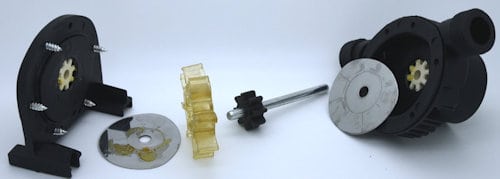
All the body is made of two plastic injected parts, maintained by 6 screws and sealed by one o-ring. The screws are here very basic Philips-like screws, which is welcome in such applications, as the user will possibly have to dismount to clean the inside.
The 2 feet of the cover give some possibilities of fixing the pump, but too small for holding the pump plus the drill.
Material is a fiber-glass-reinforced plastic; no marking of the plastic-type so as a recyclable label.
The screws slots and blades could have been integrated together in the design; currently, it looks as if one feature has been placed independently from the other.
Some marking or brand has been removed (change of owner or a low-cost OEM variant of another branded product?)
A special passage on the back through the blades radially towards one side of the stand: is that an old feature like a place for a rotation sensor or to detect if running dry? no idea !?
Inlet and outlet sealing surfaces are not very great. Users will have to have a soft and large sealing to be leak tight.
Not very convinced by the cooling blades: plastic would here act more as an additional insulator, but at least give high rigidity to the product.

Rotor construction
The shaft is inserted into a plastic gear, which itself holds the main flexible rotor (see detailed high-res pictures).
20 ejectors are required to take this soft part (kind or silicone) out of the mold.
Two nickel sheets are placed on each side of the rotor. Their low Ra permits some interference to achieve a relative leak tightness, but reduces abrasive, thus increasing the lifetime of the rotor. The edges shape is typical of a punch/cut technic.

Flow sensor analogy
We could not resist the parallel review of a water flow sensor which has much in common, from a design point of view.
This is a water flow sensor, with just the sensing element without any signal conditioning, sold to end user price for less than $2.
See the detailed gallery below for its design. A simple magnetic field sensor is detecting the change of field inducted by a small magnet attached to the turbine.
our view only: a SMD component, together with a SMD resistor would have achieved the same function (and likely more reliable to vibration and permit to reduce the PCB size by 75% ion surface. Just the PCB would require its mount rotated by 90° and housing adapted. Our hypothesis only : this product has other more sophisticated variuants where the PCB is different, maybe incorporating some signal conditioning?
In comparison with the pump design, the rotor does not have any perfect sealing, thus limiting all frictions and wearing, both with the axis and the housing.
Inlet & outlet threads and much better molded but not much on the other closing surfaces (non-functional in this case).
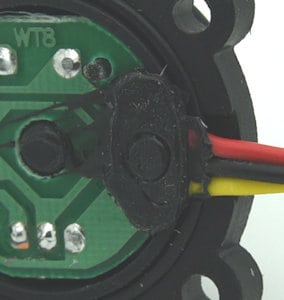
If that kind of design would have to be used in other applications, the only recommendation would be to improve the sealing method if the cable is subjected to movements or the part is to be dismounted.
The O-ring is of no concern, but as part of the sealing is obtained with some potting on the cable being pressed between the two parts and curing in position, should the cable move or the part be dismounted & the sealing will become inefficient.
Improvements and Innovations
Although this product is intended to be low cost, as a direct small improvement, the inlet and outlet’s bad surface quality should be improved; that would add not product cost, but a small work on the mold quality.
But some other modifications could add value to the product & render it even more versatile:
- an integrated inlet filter would be nice to protect the pump & very welcome as this pump is likely to be used in any harsh condition (see this design for a nice filter example)
- Without being fixed, this pump will not work safely when connected to the drill. So some more fixing possibilities on external equipment would ease its usage a lot:
- on inlet and outlet shape, maybe with some squared flanges (simply plastic shapes in the mold)
- on a vice, by providing 2 opposite parallel surfaces on the bottom
- more complicated & bigger parts, but to fixed part of the drill itself. This would require several adjustable parts, but would make the total assembly self-sufficient; possibly not an entry-level OEM accessory anymore.
- some better cooling, either
- by making one of the plastic parts in aluminum; in order to keep the price low, the one in aluminum, with cooling blades, should probably be located on the cover side (currently the blades are on the main body supporting the inlet and outlet threads)
- by attaching a small fan on the main axis; an additional sealing would then be required on the protruding axis. For security reasons, an additional small plastic cage would then be needed
- so better flow characteristics or an increased lifetime of the rotor could be achieved by inserting a nickel plate on the circular surface of the housing where the extremities of the vanes apply. This plate would need to be curved and likely bent at both ends to maintain the housing and avoid cutting the vanes. Depending if the plate includes two holes for the inlet & outlet or not, the plate could cover 3/4 of the turn or the full periphery.
Glossary of Terms Used
Original Equipment Manufacturer (OEM): a company that produces parts or equipment that may be marketed by another manufacturer. Typically, these components are integrated into the final product, which is then sold under the latter's brand name.
Printed Circuit Board (PCB): a flat board made of insulating material that supports and connects electronic components through conductive pathways, typically etched from copper sheets. It serves as a foundation for circuit assembly and facilitates electrical connections between components.










1 thought on “Handyman pump design review”
Isnt the rotor construction just as important as product design? Cant ignore the flow sensor analogy either, right guys?