Soutenir la spécification, l'analyse et la conception, vérification, et validation d'un large éventail de systèmes et de systèmes de systèmes.
- Méthodologies : Ergonomie
Diagrammes SysML
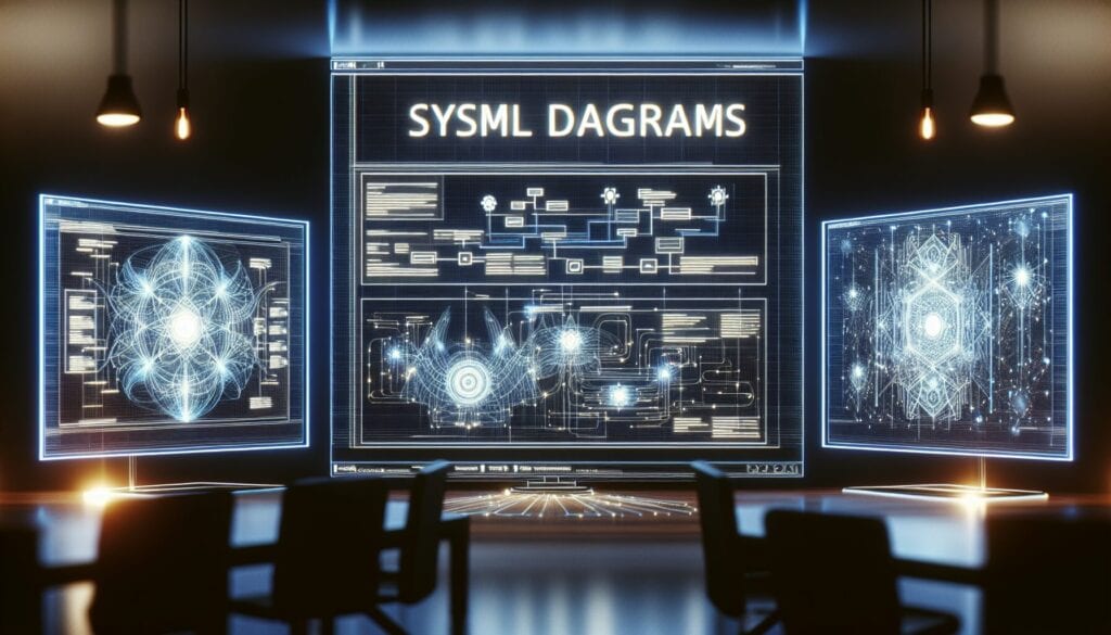
Diagrammes SysML
- Méthodologie Agile, Conception pour la durabilité, Ingénierie des systèmes basée sur des modèles (MBSE), Amélioration des processus, Gestion de projet, Gestion de la qualité, Langage de modélisation des systèmes (SysML), Langage de modélisation unifié (UML), Vérification et validation
Objectif :
Comment il est utilisé :
Avantages
- Fournit un moyen normalisé de représenter les systèmes ; facilite la communication et la collaboration entre les différentes disciplines d'ingénierie ; soutient l'ingénierie des systèmes basée sur les modèles (MBSE) ; aide à gérer la complexité.
Inconvénients
- Peut être complexe à apprendre et à utiliser efficacement ; nécessite des outils de modélisation spécialisés ; peut être perçu comme trop formel pour les petits projets ; risque de "gonflement du langage" en raison de son exhaustivité et de l'héritage UML.
Catégories :
- Ingénierie, Conception de Produits, Gestion de projet, Gestion des risques
Idéal pour :
- Modéliser et gérer des systèmes complexes et multidisciplinaires tout au long de leur cycle de vie.
SysML diagrams find extensive applications across various industries such as aerospace, automotive, defense, healthcare, and telecommunications, where the design and integration of complex systems are commonplace. During the requirements phase of a project, stakeholders can utilize requirement diagrams to capture and organize user needs, ensuring clarity in what the end product must achieve. The block definition diagram is particularly beneficial in early design stages for representing the system architecture, facilitating discussions among engineers about component interrelations before proceeding to detailed design. Internal block diagrams can then be used in the development phase to illustrate the interactions between components at a deeper level, which can prove invaluable when conducting trade studies and system verification. Parametric diagrams come into play for performance analysis, enabling engineers to evaluate constraints and parameters that define system behavior under various conditions. Typically, a cross-disciplinary team comprising systems engineers, software developers, hardware engineers, and project managers collaborates on these diagrams to ensure that all facets of the design are aligned and that the integration challenges are addressed early on. Utilizing SysML enables model-based systems engineering, which reinforces a holistic view of the project while addressing interdisciplinary requirements, thus enhancing collaboration and reducing the likelihood of costly miscommunications during later stages. The standardization of representations across different teams accelerates the overall workflow, making it easier to share models and documentation through various phases of the system lifecycle, from conceptualization to deployment and maintenance.
Principales étapes de cette méthodologie
- Define system requirements using requirement diagrams to capture stakeholder needs.
- Create block definition diagrams to represent system elements and their relationships.
- Develop internal block diagrams to illustrate internal system structure and connectivity.
- Construct parametric diagrams to define performance constraints and relationships among system properties.
- Use sequence diagrams to detail interactions and workflows between components.
- Iterate through diagrams as needed to refine and validate system models continuously.
- Integrate and verify models across different engineering disciplines to ensure alignment.
- Conduct reviews and assessments to evaluate system design and functionality against requirements.
Conseils de pro
- Utilize cross-discipline collaboration sessions to review SysML models, ensuring alignment and addressing discrepancies early in the design phase.
- Leverage the power of parametric diagrams to quantify and validate system performance criteria, providing tangible metrics that guide design decisions.
- Integrate version control tools with your SysML models to track changes over time, facilitating better management of systemic evolution and decision-making processes.
Lire et comparer plusieurs méthodologies, nous recommandons le
> Référentiel méthodologique étendu <
ainsi que plus de 400 autres méthodologies.
Vos commentaires sur cette méthodologie ou des informations supplémentaires sont les bienvenus sur le site web de la Commission européenne. section des commentaires ci-dessous ↓ , ainsi que toute idée ou lien en rapport avec l'ingénierie.
Contexte historique


1980
1980
1986
1987
1990
1990
1990
1980
1980
1986
1986
1987-03
1990
1990
1992


(si la date est inconnue ou n'est pas pertinente, par exemple "mécanique des fluides", une estimation arrondie de son émergence notable est fournie)
Articles Similaires
Questionnaires sur les troubles musculo-squelettiques
Tests à plusieurs variables (MVT)
Analyse de régression multiple
Systèmes de capture de mouvement
Méthode MoSCoW
Test de la médiane de Mood