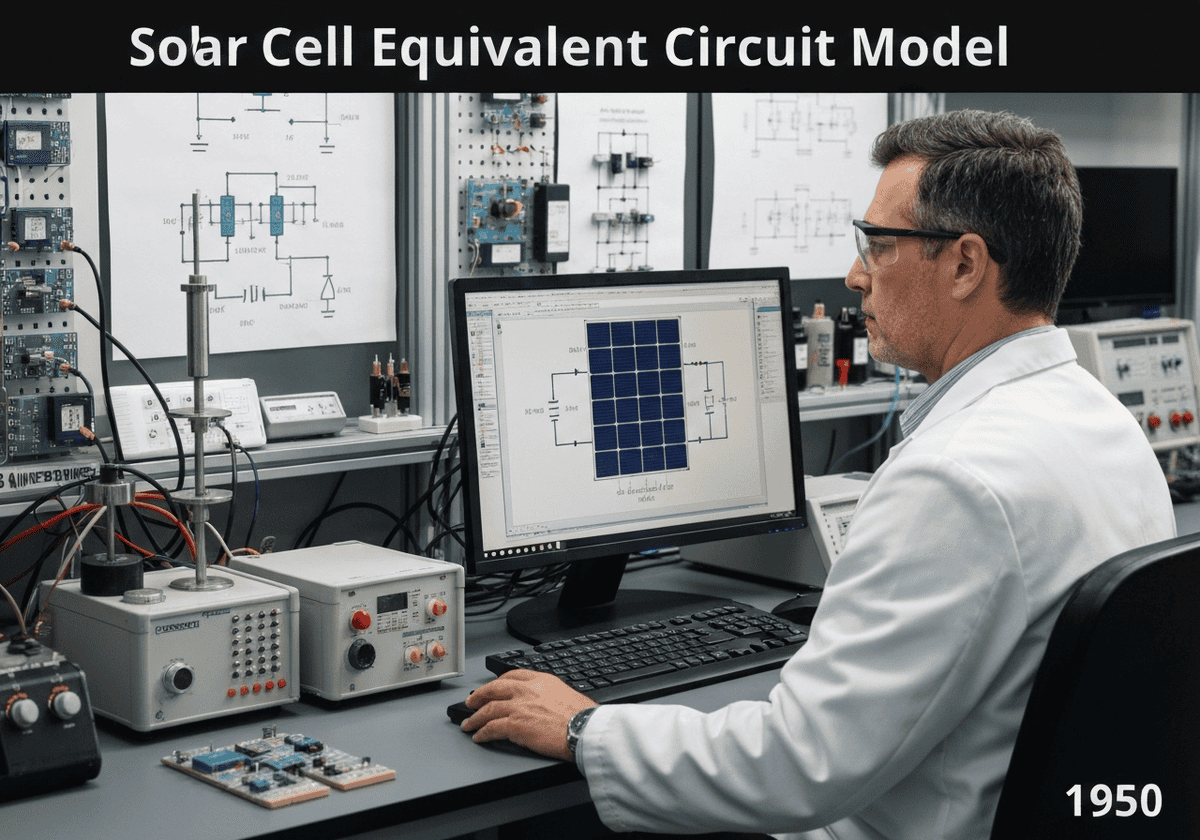
A solar cell can be modeled by an equivalent electrical circuit. The simplest model includes a current source representing the photogenerated current ([latex]I_L[/latex]), in parallel with a diode representing the p-n junction. A more accurate model adds a parallel shunt resistance ([latex]R_{sh}[/latex]) for leakage currents and a series resistance ([latex]R_s[/latex]) for contact and bulk material resistance.
Solar Cell Equivalent Circuit Model
The equivalent circuit model is a powerful tool for understanding and analyzing the electrical behavior of a solar cell. It abstracts the complex semiconductor physics into a simple circuit diagram with a few key components. The core of the model is an ideal current source that produces a current, [latex]I_L[/latex], directly proportional to the incident light intensity. This represents the generation of electron-hole pairs by photons.
In parallel with this current source is a diode. This diode models the behavior of the p-n junction itself. In the dark, the solar cell is just a diode, and its current-voltage (I-V) characteristic follows the ideal diode equation. When illuminated, some of the photogenerated current is shunted through this internal diode, a process known as recombination, which does not contribute to the output current. The total output current [latex]I[/latex] is therefore the photogenerated current minus the diode current: [latex]I = I_L – I_D[/latex].
For a more realistic representation, two parasitic resistances are added. A series resistance, [latex]R_s[/latex], accounts for the resistance of the metal contacts, the emitter, and the bulk semiconductor material. It causes a voltage drop that reduces the terminal voltage and the fill factor. A shunt resistance, [latex]R_{sh}[/latex], is placed in parallel with the diode and current source. It represents leakage paths for the current across the p-n junction, often due to fabricación defects. A low shunt resistance provides an alternate path for the photogenerated current, reducing the current delivered to the load. The governing equation for this single-diode model is: [latex]I = I_L – I_0 \left[ \exp\left(\frac{V+IR_s}{n k_B T/q}\right) – 1 \right] – \frac{V+IR_s}{R_{sh}}[/latex], where [latex]I_0[/latex] is the diode saturation current and [latex]n[/latex] is the ideality factor.
Tipo
Disruption
Utilización
Precursors
- development of diode theory (shockley diode equation)
- ohm’s law
- kirchhoff’s circuit laws
- invention of the p-n junction solar cell
Aplicaciones
- predicting solar cell performance under varying conditions
- characterizing solar panels in manufacturing (i-v curve tracing)
- designing maximum power point tracking (mppt) algorithms
- simulating the behavior of large photovoltaic arrays
Patentes:
Potential Innovations Ideas
Membresía obligatoria de Professionals (100% free)
Debes ser miembro de Professionals (100% free) para acceder a este contenido.
DISPONIBLE PARA NUEVOS RETOS
Ingeniero Mecánico, Gerente de Proyectos o de I+D
Disponible para un nuevo desafío a corto plazo.
Contáctame en LinkedIn
Integración de electrónica de plástico y metal, diseño a coste, GMP, ergonomía, dispositivos y consumibles de volumen medio a alto, industrias reguladas, CE y FDA, CAD, Solidworks, cinturón negro Lean Sigma, ISO 13485 médico
Estamos buscando un nuevo patrocinador
¿Su empresa o institución se dedica a la técnica, la ciencia o la investigación?
> Envíanos un mensaje <
Recibe todos los artículos nuevos
Gratuito, sin spam, correo electrónico no distribuido ni revendido.
o puedes obtener tu membresía completa -gratis- para acceder a todo el contenido restringido >aquí<
Historical Context
Solar Cell Equivalent Circuit Model
(if date is unknown or not relevant, e.g. "fluid mechanics", a rounded estimation of its notable emergence is provided)
Related Invention, Innovation & Technical Principles