Heim » Beste KI-Eingabeaufforderungen für die Elektrotechnik

Beste KI-Eingabeaufforderungen für die Elektrotechnik

KI beflügelt Elektrotechnik
KI-Aufforderungen für die Elektrotechnik
KI-gesteuerte Werkzeuge revolutionieren die Elektrotechnik, indem sie durch fortschrittliche Datenanalyse und generative Entwurfstechniken die Entwurfseffizienz, die Simulationsgenauigkeit und die vorausschauende Wartung verbessern.

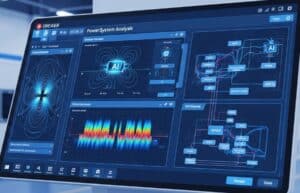
Online-KI-Tools verändern die Elektrotechnik rapide, indem sie die menschlichen Fähigkeiten bei der Schaltungsentwicklung, der Systemanalyse und der Elektronik ergänzen. Herstellungund die Wartung von Stromversorgungssystemen. Diese KI-Systeme können große Mengen an Simulationsdaten, Sensormesswerten und Netzwerkverkehr verarbeiten, komplexe Anomalien oder Leistungsengpässe erkennen und neuartige Schaltungstopologien oder Steuerungsalgorithmen viel schneller als herkömmliche Methoden entwickeln. KI kann Sie beispielsweise bei der Optimierung von PCB-Layouts im Hinblick auf Signalintegrität und Herstellbarkeit unterstützen, komplexe elektromagnetische oder Leistungsflusssimulationen beschleunigen, die Eigenschaften von Halbleiterbauelementen vorhersagen und eine Vielzahl von Aufgaben automatisieren. Signalverarbeitung und Datenanalyseaufgaben.

Die nachstehenden Aufforderungen helfen beispielsweise beim generativen Entwurf von Antennen oder Filtern, beschleunigen Simulationen (SPICE, EM-Feldsimulationen, Stabilitätsanalysen von Stromversorgungssystemen), helfen bei der vorausschauenden Wartung, bei der KI Sensordaten von Leistungstransformatoren oder Netzkomponenten analysiert, um potenzielle Ausfälle vorherzusagen, was eine proaktive Wartung ermöglicht und Ausfallzeiten minimiert, helfen bei der Auswahl von Halbleitermaterialien oder optimalen Komponenten (z. B. Auswahl des besten Operationsverstärkers für bestimmte Parameter) und vieles mehr.

  • Angesichts der Server-Ressourcen und des Zeitaufwands sind die Eingabeaufforderungen selbst nur registrierten Mitgliedern vorbehalten und unten nicht sichtbar, wenn Sie nicht angemeldet sind. Sie können sich registrieren, 100% kostenlos: 

Mitgliedschaft erforderlich

Sie müssen Mitglied sein, um auf diesen Inhalt zugreifen zu können.

Mitgliederstufen anzeigen

Sie sind bereits Mitglied? Hier einloggen

AI Aufforderung an Erstellen einer Bibliographie bahnbrechender Arbeiten

Mit dieser Eingabeaufforderung wird die KI angewiesen, eine Bibliografie der wichtigsten Arbeiten in einem bestimmten Teilgebiet der Elektrotechnik zu erstellen. Der Benutzer gibt das Teilgebiet und optional Filter wie Datum oder Autoren ein.

Ausgabe: 

				
					Generate a CSV bibliography list of seminal papers in the electrical engineering subfield: 
 {electrical_subfield} 
 applying these filters if any: 
 {filters} 
 The CSV must include columns: PaperTitle, Authors, Year, JournalOrConference, DOI or URL. Sort by relevance and citation count if possible.
							

AI Aufforderung an Analysieren Sie die Entwicklung der elektrotechnischen Technologien

Diese Aufforderung fordert die KI auf, die historische Entwicklung und die Zukunftsaussichten einer bestimmten elektrotechnischen Technologie oder eines Konzepts zu analysieren. Der Benutzer gibt den Namen der Technologie und den Zeitrahmen an.

Ausgabe: 

				
					Analyze the historical development and evolution of the following electrical engineering technology: 
 {technology_name} 
 over this timeline: 
 {timeline} 
 Provide a markdown formatted report including key milestones, technological advances, influential researchers, and predicted future trends. Use headings, bullet points, and timeline tables where appropriate.
							

AI Aufforderung an Identifizierung von Risiken im elektrischen System

Diese Eingabeaufforderung hilft bei der Ermittlung potenzieller Risiken und Fehlermöglichkeiten in einem bestimmten elektrischen System oder einer Komponente. Der Benutzer gibt die Systembeschreibung und die Betriebsbedingungen ein, und die KI gibt eine strukturierte Risikoliste mit Bewertungen des Schweregrads und der Eintrittswahrscheinlichkeit aus.

Ausgabe: 

				
					Based on the following electrical system description: 
 {electrical_system_description} 
 and the operating conditions: 
 {operating_conditions} 
 identify all potential risks, failure modes, and hazards. For each risk, provide an assessment of severity (High, Medium, Low) and likelihood (High, Medium, Low). Format the output as a JSON array with objects containing RiskDescription, Severity, Likelihood, and SuggestedMitigation.
							

AI Aufforderung an Bewertung von Sicherheitsmaßnahmen für die elektrische Konstruktion

Diese Eingabeaufforderung weist die KI an, die Wirksamkeit der angegebenen Sicherheitsmaßnahmen in einem elektrischen Entwurf auf der Grundlage der angegebenen Konstruktionsdetails und Normen zu bewerten. Der Benutzer gibt Konstruktionsmerkmale und relevante Sicherheitsnormen ein.

Ausgabe: 

				
					Given the electrical design features: 
 {design_features} 
 and the following safety standards: 
 {safety_standards} 
 evaluate the adequacy of the implemented safety measures. Provide a detailed markdown report with sections for compliance, potential weaknesses, and recommendations for improvement. Use bullet points and bold important terms.
							

AI Aufforderung an Quantitative Risikoanalyse für elektrische Systeme

Diese Aufforderung fordert die KI auf, eine quantitative Risikoanalyse für ein bestimmtes elektrisches System durchzuführen, wobei Eingabedaten wie Ausfallraten und Expositionszeiten verwendet werden. Der Benutzer gibt Fehlerdaten und Systemparameter ein.

Ausgabe: 

				
					Using the following failure rates data in CSV format: 
 {failure_rates_data} 
 and system parameters: 
 {system_parameters} 
 calculate quantitative risk metrics such as Failure Probability, Risk Priority Number (RPN), and expected downtime. Return a CSV table with columns: Component, FailureRate, Severity, Occurrence, Detection, RPN, MitigationActions. Explain calculations briefly in comments if possible.
							

AI Aufforderung an Vorschlagen von Abhilfestrategien für elektrische Gefahren

Diese Eingabeaufforderung ermöglicht es der KI, praktische Abhilfestrategien für identifizierte elektrische Gefahren in einer bestimmten Einrichtung vorzuschlagen. Der Benutzer gibt die Gefahrenliste und den Systemkontext an.

Ausgabe: 

				
					Given the following list of electrical hazards: 
 {hazard_list} 
 and the system context: 
 {system_context} 
 suggest detailed and practical mitigation strategies to reduce risks. Include engineering controls, administrative controls, and personal protective equipment recommendations. Structure the response with headings and bullet points.
							

AI Aufforderung an Abstimmung der Parameter des SPICE-MOSFET-Modells

Führt die KI dazu, SPICE-Modellparameteranpassungen für einen bestimmten MOSFET vorzuschlagen, um dessen Datenblatt oder Zielanwendungsleistung besser zu entsprechen. Dies hilft bei der Erstellung genauerer Simulationen für den Schaltungsentwurf. Die Ausgabe ist ein JSON-Objekt mit vorgeschlagenen Parameterwerten und Begründungen.

Ausgabe: 

				
					Act as a Semiconductor Device Modeling Engineer.
Your TASK is to suggest SPICE model parameter adjustments for the MOSFET identified by `{mosfet_part_number_or_datasheet_url}` to better align its simulation behavior with datasheet specifications or the needs of a `{target_application_focus}` (e.g.
 'High-frequency SMPS'
 'RF amplifier stage'
 'Low RDS(on) switching').
The goal is to match key performance metrics listed in `{key_performance_metrics_to_match_csv}` (e.g.
 'RDS(on)_at_Vgs=10V
Gate_Threshold_Voltage_Vth
Total_Gate_Charge_Qg
Output_Capacitance_Coss
Switching_Times_tr_tf').

**ANALYSIS AND SUGGESTION LOGIC:**
1.  **Datasheet Review (if URL/Part Number provided for live access):**
    *   Attempt to fetch and review the datasheet for `{mosfet_part_number_or_datasheet_url}`.
    *   Extract typical values for the `{key_performance_metrics_to_match_csv}`.
2.  **Identify Key SPICE Parameters:**
    *   Based on a standard MOSFET model (e.g.
 LEVEL 1
 LEVEL 3
 BSIM)
 identify SPICE parameters that MOST STRONGLY influence the `{key_performance_metrics_to_match_csv}`. Examples:
        *   `VTO` (Zero-bias threshold voltage) -> Vth
        *   `KP` (Transconductance parameter)
 `LAMBDA` (Channel-length modulation) -> RDS(on)
 I-V curves.
        *   `CGSO`
 `CGDO`
 `CGBO` (Gate overlap capacitances) -> Qg
 Coss
 Crss.
        *   `RD`
 `RS` (Drain/Source ohmic resistances) -> RDS(on).
        *   `TOX` (Gate oxide thickness) -> Affects VTO
 capacitances.
        *   Parameters influencing switching times (internal resistances
 capacitances).
3.  **Suggest Adjustments:**
    *   For each relevant SPICE parameter
 suggest a direction for adjustment (increase/decrease) or a target range if a generic model is being tuned.
    *   Provide a brief RATIONALE for each suggested adjustment
 linking it back to the `{key_performance_metrics_to_match_csv}` and `{target_application_focus}`.
    *   If a specific SPICE model level is assumed (e.g.
 BSIM4)
 mention it.

**OUTPUT FORMAT (JSON):**
Return a single JSON object structured as follows:
`{
  "mosfet_model_tuning_suggestions": {
    "target_mosfet": "`{mosfet_part_number_or_datasheet_url}`"
    "assumed_spice_model_level": "[e.g.
 BSIM4
 Level 3
 Generic Power MOSFET]"
    "parameter_adjustments": [
      {
        "spice_parameter": "VTO"
        "suggested_value_or_adjustment": "[e.g.
 Target 2.5V based on datasheet Vth
 or 'Slightly decrease if simulated Vth is too high']"
        "rationale": "Directly impacts gate threshold voltage
 critical for matching turn-on characteristics for `{target_application_focus}`."
        "related_metric": "Gate_Threshold_Voltage_Vth"
      }
      {
        "spice_parameter": "KP"
        "suggested_value_or_adjustment": "[e.g.
 Increase if simulated RDS(on) is too high]"
        "rationale": "Impacts channel conductivity and thus RDS(on) and current handling."
        "related_metric": "RDS(on)"
      }
      {
        "spice_parameter": "CGDO"
        "suggested_value_or_adjustment": "[e.g.
 Adjust to match Miller plateau in Qg curve or Crss from datasheet]"
        "rationale": "Gate-Drain capacitance significantly affects switching speed and total gate charge."
        "related_metric": "Total_Gate_Charge_Qg
Switching_Times_tr_tf"
      }
      // ... more parameter suggestions ...
    ]
    "general_tuning_notes": "Start with major DC parameters (VTO
 KP
 RDS(on))
 then refine AC/switching parameters (capacitances
 gate resistance). Iterative adjustments and comparison with datasheet curves are recommended. Consider temperature effects if relevant for `{target_application_focus}`."
  }
}`

**IMPORTANT**: The suggestions should be practical for an engineer working with SPICE models. If the AI cannot access the datasheet
 it should base suggestions on general knowledge of MOSFET parameters and their influence on the listed metrics.
							

AI Aufforderung an Phased Array-Antennen-Simulationsaufbau

Umreißt die wichtigsten Schritte und Parameter für die Einrichtung einer elektromagnetischen Simulation einer phasengesteuerten Gruppenantenne mit dem Ziel, das Fernfeld-Strahlungsdiagramm und die Scanleistung zu berechnen. Diese Aufforderung hilft Antenneningenieuren, ihre EM-Simulationen zu strukturieren. Die Ausgabe ist eine Markdown-Checkliste.

Ausgabe: 

				
					Act as an Antenna Simulation Specialist using a generic EM solver (e.g.
 HFSS
 CST
 Feko).
Your TASK is to outline the setup for simulating a phased array antenna with `{number_of_elements}` elements
 spaced by `{element_spacing_wavelengths}` (in wavelengths).
The array is intended to be scanned to `{scan_angle_degrees_theta_phi}` (theta
 phi in degrees) at an operating frequency of `{operating_frequency_ghz}` GHz.
The primary goal is to determine the array's far-field radiation pattern and gain.

**SIMULATION SETUP CHECKLIST (Markdown format):**

**1. Element Definition & Simulation (if not using an ideal element pattern):**
    *   `[ ]` **Define Single Element Geometry**: Create the 3D model of a single antenna element (e.g.
 patch
 dipole
 horn). Specify materials.
    *   `[ ]` **Assign Port/Excitation**: Define a port for the single element.
    *   `[ ]` **Boundary Conditions for Single Element**: Use appropriate boundaries (e.g.
 PML or radiation boundary for standalone element simulation).
    *   `[ ]` **Solve Single Element**: Simulate the standalone element at `{operating_frequency_ghz}` GHz to obtain its embedded pattern or S-parameters if needed for array analysis.
    *   `[ ]` **Extract Element Pattern**: Save the far-field pattern of the single element if it will be used in an array factor calculation.

**2. Array Configuration & Excitation:**
    *   `[ ]` **Define Array Geometry**:
        *   Specify array type (e.g.
 linear
 planar rectangular
 circular). Assume linear or rectangular if not specified.
        *   Arrange `{number_of_elements}` elements with the specified `{element_spacing_wavelengths}`.
    *   `[ ]` **Calculate Element Phase Shifts for Scanning**:
        *   Determine the progressive phase shift (`alpha`) required for each element to steer the beam to `{scan_angle_degrees_theta_phi}`.
        *   Formula hint: For a linear array along x-axis
 `alpha = -k * d * sin(theta_scan_desired)`
 where `k = 2*pi/lambda` and `d` is element spacing from `{element_spacing_wavelengths}`.
    *   `[ ]` **Apply Excitations to Array Elements**:
        *   Set the magnitude of excitation for each element (typically uniform unless amplitude tapering is used for sidelobe control).
        *   Set the phase of excitation for each element according to the calculated progressive phase shift for the desired `{scan_angle_degrees_theta_phi}`.
    *   `[ ]` **(Alternative if simulating full array directly)** Define individual ports for each element in the full array model.

**3. Full Array Simulation Setup (if not using Array Factor approach):**
    *   `[ ]` **Enclose Full Array**: Define a radiation boundary (PML
 absorbing
 far-field box) sufficiently large around the entire array.
    *   `[ ]` **Mesh Settings**: Ensure mesh is fine enough around elements and in regions of strong fields
 particularly at `{operating_frequency_ghz}`. Consider mesh convergence study.

**4. Solution Setup:**
    *   `[ ]` **Frequency Sweep**: Define solution frequency around `{operating_frequency_ghz}` GHz. A single frequency point is fine for pattern
 or a narrow band for S-parameters.
    *   `[ ]` **Solver Type**: Choose appropriate solver (e.g.
 FEM
 MoM
 FDTD).
    *   `[ ]` **Convergence Criteria**: Set appropriate criteria for solver convergence.

**5. Post-Processing & Results Extraction:**
    *   `[ ]` **Far-Field Radiation Pattern**: Calculate and plot 2D (azimuth/elevation cuts) and 3D far-field patterns.
    *   `[ ]` **Key Metrics**:
        *   Peak Gain / Directivity at `{scan_angle_degrees_theta_phi}`.
        *   3dB Beamwidth in principal planes.
        *   Sidelobe Levels (SLL).
        *   Grating Lobe locations (check if spacing and scan angle cause them).
    *   `[ ]` **Input Impedance / S-parameters**: Check active input impedance of elements if full array is simulated with individual ports.
    *   `[ ]` **Array Factor (if used)**: If using array factor + element pattern
 combine them correctly.

**6. Parametric Sweeps / Optimization (Optional Next Steps):**
    *   `[ ]` Sweep scan angle to observe pattern changes.
    *   `[ ]` Vary element spacing or amplitude/phase distributions to optimize performance (e.g.
 for lower sidelobes).

**IMPORTANT**: If simulating a large array
 consider using domain decomposition
 finite array assumptions
 or array factor techniques if full-wave simulation of all elements is computationally prohibitive. Ensure consistency in coordinate systems.
							

AI Aufforderung an PCB Crosstalk Analysis Parameter Setup

Umreißt die wichtigsten Parameter und Setup-Überlegungen für die Durchführung einer PCB-Crosstalk-Simulation mit Schwerpunkt auf kritischen Netzen angesichts ihrer Eigenschaften und PCB-Stackup-Informationen. Dies hilft Ingenieuren bei der Konfiguration von SI-Simulationen zur Vorhersage und Minderung von Nebensprechen. Die Ausgabe ist ein Markdown-Bericht mit detaillierten Parametern und Vorschlägen.

Ausgabe: 

				
					Act as a Signal Integrity (SI) Simulation Specialist.
Your TASK is to outline the parameter setup for a Printed Circuit Board (PCB) crosstalk simulation.
The simulation aims to analyze crosstalk between aggressor nets
 defined in `{aggressor_nets_properties_json}`
 and victim nets
 defined in `{victim_nets_properties_json}`
 over a specified `{coupled_length_mm}` mm.
The PCB construction is described by `{pcb_stackup_description_text}` (e.g.
 '4-layer: Signal1 (Top
 1oz Cu
 Dielectric Er=4.2
 H1=0.2mm)
 GND
 PWR
 Signal2 (Bottom
 1oz Cu
 Dielectric Er=4.2
 H2=0.2mm from PWR)').
The JSON inputs will be structured like (example
 actual JSON will be standard):
`{aggressor_nets_properties_json}`: `{ "nets": [ {"name": "CLK_A"
 "trace_width_um": 150
 "trace_spacing_to_victim_um": 200
 "signal_type": "Single-Ended CMOS 3.3V"
 "rise_time_ps": 500} ] }`
`{victim_nets_properties_json}`: `{ "nets": [ {"name": "DATA_X"
 "trace_width_um": 150
 "termination_ohms": 50} ] }`

**CROSSTALK SIMULATION SETUP PARAMETERS (Markdown format):**

**1. Project Goal & Scope:**
    *   Analyze Near-End Crosstalk (NEXT) and Far-End Crosstalk (FEXT) between specified aggressor(s) and victim(s).
    *   Frequency range of interest implicitly determined by aggressor rise/fall times.

**2. Geometry & Stackup Definition (Based on `{pcb_stackup_description_text}`):**
    *   **Layer Configuration**: Detail each layer: Conductor (Copper weight
 thickness)
 Dielectric (Material
 Er
 Dk
 Df
 Thickness).
        *   Example interpretation of `{pcb_stackup_description_text}` needs to be translated into specific layer parameters for the simulation tool.
    *   **Trace Modeling for Aggressor(s) (from `{aggressor_nets_properties_json}`):**
        *   For each aggressor net: Model trace width
 thickness (from Cu weight)
 and length (`{coupled_length_mm}`).
        *   Layer assignment based on `{pcb_stackup_description_text}` (e.g.
 microstrip
 stripline).
    *   **Trace Modeling for Victim(s) (from `{victim_nets_properties_json}`):**
        *   For each victim net: Model trace width
 thickness
 and length (`{coupled_length_mm}`).
        *   Relative spacing to aggressor(s) as per `{aggressor_nets_properties_json}`.
    *   **Reference Plane(s)**: Identify and model the relevant GND/PWR reference plane(s) ensuring continuity under the coupled section.

**3. Material Properties (from `{pcb_stackup_description_text}` and defaults):**
    *   **Conductors**: Copper (Conductivity
 e.g.
 5.8e7 S/m). Include surface roughness models if high frequencies are involved (e.g.
 Hammerstad
 Groisse).
    *   **Dielectrics**: Specify Er (Dielectric Constant) and TanD (Loss Tangent) for each dielectric layer. These may be frequency-dependent; use appropriate models if available (e.g.
 Wideband Debye
 Djordjevic-Sarkar).

**4. Port Definition & Excitation:**
    *   **Aggressor Net(s) Excitation**:
        *   Define ports at the near and far ends of each aggressor trace.
        *   Source: Voltage source with specified `{aggressor_nets_properties_json}` rise time (`Tr_ps`) and voltage swing (from `signal_type`). Use a pulse or step waveform.
        *   Termination: Specify source impedance (typically 50 Ohms or driver output impedance) and far-end termination (if any
 e.g.
 open
 specific resistance).
    *   **Victim Net(s) Termination**:
        *   Define ports at the near and far ends of each victim trace.
        *   Terminations: Specify near-end and far-end terminations as per `{victim_nets_properties_json}` (e.g.
 50 Ohms
 high-Z input of a receiver).

**5. Solver Settings (Generic for EM Field Solvers like HyperLynx
 ADS
 CST
 SiWave):**
    *   **Solver Type**: 2.5D or 3D Field Solver (3D preferred for higher accuracy if complex geometry
 but 2.5D might be faster for simpler trace coupling).
    *   **Frequency Range for Solution**:
        *   Set DC point (0 Hz).
        *   Maximum frequency: At least `0.35 / Tr_ns` (or `0.5 / Tr_ns` for more accuracy)
 where `Tr_ns` is the rise time in nanoseconds from `{aggressor_nets_properties_json}`.
        *   Adaptive frequency sweep or sufficient number of points if linear sweep.
    *   **Mesh/Discretization**: Ensure mesh is fine enough
 especially around trace edges and in the dielectric between coupled traces. Perform a mesh convergence study if unsure.
    *   **Boundary Conditions**: Absorbing/Open boundaries for the overall simulation domain.

**6. Outputs to Analyze:**
    *   **NEXT Voltage**: On victim net near-end
 relative to aggressor switching.
    *   **FEXT Voltage**: On victim net far-end
 relative to aggressor switching.
    *   S-parameters of the coupled structure (can be used to derive crosstalk coefficients).
    *   Time-domain waveforms on victim net ports.
    *   Impedance plots of the traces.

**7. Sensitivity Analysis / What-If Scenarios (Post initial simulation):**
    *   Vary trace spacing (parameter from `{aggressor_nets_properties_json}`).
    *   Vary coupled length (`{coupled_length_mm}`).
    *   Vary dielectric height/Er.
    *   Introduce guard traces between aggressor and victim.

**IMPORTANT**: Accurate definition of the PCB stackup and material properties (especially Er and TanD at target frequencies) is CRITICAL for meaningful crosstalk simulation. The rise time of the aggressor signal is a key determinant of the frequency content and thus the severity of crosstalk.
							

AI Aufforderung an Kalman-Filter für Sensorfusion erklärt

Erläutert die grundlegenden Prinzipien der Kalman-Filterung, angewandt auf die Sensorfusion in einem elektrotechnischen Kontext (z.B. Navigation IMU+GPS Robotik). Es behandelt die Definition von Zustandsvektoren, Kovarianzmatrizen und den Vorhersage-Aktualisierungszyklus. Die Ausgabe ist ein Markdown-Dokument mit Gleichungen (wenn möglich in LaTeX).

Ausgabe: 

				
					Act as a University Professor of Control Systems and Estimation Theory.
Your TASK is to provide a clear and detailed explanation of the Kalman Filter algorithm
 specifically as it's applied to sensor fusion in the electrical engineering `{application_context_description}` (e.g.
 'UAV navigation using IMU and GPS data'
 'Robot localization with wheel encoders and LIDAR'
 'Power system state estimation with SCADA and PMU data').
The explanation should consider the types of sensors being fused
 listed in `{sensors_being_fused_list_csv}` (e.g.
 'IMU_Accelerometer_Gyroscope
GPS_Position_Velocity
Magnetometer')
 and focus on the `{key_aspect_to_clarify}` (e.g.
 'Definition of the state vector and state transition matrix'
 'Role and tuning of Q and R covariance matrices'
 'The predict-update cycle and Kalman gain calculation'
 'Assumptions and limitations of the standard Kalman Filter').

**EXPLANATION OF KALMAN FILTER FOR SENSOR FUSION (Markdown format):**

**1. Introduction to Kalman Filtering in `{application_context_description}`**
    *   What is sensor fusion and why is it important for `{application_context_description}`?
    *   Briefly
 what is the Kalman Filter? (Optimal recursive data processing algorithm for estimating the state of a dynamic system from noisy measurements).
    *   How it helps fuse data from `{sensors_being_fused_list_csv}` to get a more accurate/reliable estimate than any single sensor.

**2. The Kalman Filter Model: Key Components**
    *   **State Vector (`x_k`)**: 
        *   Definition: Represents the set of variables we want to estimate at time step `k`.
        *   **Application to `{application_context_description}`**: Based on the context and `{sensors_being_fused_list_csv}`
 what would typical elements of the state vector be? (e.g.
 for UAV navigation: position (px
 py
 pz)
 velocity (vx
 vy
 vz)
 orientation (roll
 pitch
 yaw)
 sensor biases).
        *   This section should directly address the `{key_aspect_to_clarify}` if it's about state vector definition.
    *   **State Transition Model (Linear System Dynamics)**:
        *   Equation: `x_k = A * x_{k-1} + B * u_{k-1} + w_{k-1}`
        *   `A`: State transition matrix (relates previous state to current state
 e.g.
 based on physics of motion).
        *   `B`: Control input matrix (relates control input `u` to state
 e.g.
 motor commands
 actuator inputs). May not be present in all estimation problems.
        *   `u_{k-1}`: Control input vector.
        *   `w_{k-1}`: Process noise (uncorrelated
 zero-mean Gaussian
 with covariance matrix `Q`). Represents uncertainty in the process model.
    *   **Measurement Model (Linear Sensor Model)**:
        *   Equation: `z_k = H * x_k + v_k`
        *   `z_k`: Measurement vector at time `k` (from sensors in `{sensors_being_fused_list_csv}`).
        *   `H`: Measurement matrix (relates the state vector to the measurements). How do sensor readings map to states?
        *   `v_k`: Measurement noise (uncorrelated
 zero-mean Gaussian
 with covariance matrix `R`). Represents uncertainty/noise in sensor readings.
    *   **Covariance Matrices**:
        *   `P_k`: State estimate error covariance matrix (how uncertain is our state estimate?).
        *   `Q`: Process noise covariance matrix (how uncertain is our dynamic model? Tunable parameter).
        *   `R`: Measurement noise covariance matrix (how noisy are our sensors? Usually characterized from sensor datasheets or calibration. Tunable parameter).
        *   This section should directly address the `{key_aspect_to_clarify}` if it's about Q and R matrices.

**3. The Kalman Filter Algorithm: Predict-Update Cycle**
    This section should directly address the `{key_aspect_to_clarify}` if it's about the cycle or Kalman gain.
    *   **Prediction Step (Time Update - "Predicting" the next state):**
        *   Predict state estimate: `x_hat_k_minus = A * x_hat_{k-1} + B * u_{k-1}`
        *   Predict error covariance: `P_k_minus = A * P_{k-1} * A^T + Q`
    *   **Update Step (Measurement Update - "Correcting" with new measurement `z_k`):**
        *   Calculate Kalman Gain (`K_k`): 
            `K_k = P_k_minus * H^T * (H * P_k_minus * H^T + R)^{-1}`
            *   Interpretation: How much should we trust the new measurement vs. our prediction? `K_k` balances this.
        *   Update state estimate: `x_hat_k = x_hat_k_minus + K_k * (z_k - H * x_hat_k_minus)`
            *   `(z_k - H * x_hat_k_minus)` is the measurement residual or innovation.
        *   Update error covariance: `P_k = (I - K_k * H) * P_k_minus`

**4. Key Aspect Clarification: `{key_aspect_to_clarify}`**
    *   Provide a focused
 detailed explanation of the specific aspect requested by the user
 drawing from the general descriptions above and tailoring it further to the `{application_context_description}`.
    *   For example
 if it's about 'Tuning Q and R': Discuss strategies for selecting Q and R values
 their impact on filter performance (responsiveness vs. smoothness
 sensitivity to model errors vs. measurement noise)
 and common heuristic tuning methods.

**5. Assumptions and Limitations of the Standard Kalman Filter**
    *   Linear system dynamics and linear measurement model.
    *   Gaussian noise (process and measurement noise must be Gaussian).
    *   Known system parameters (A
 B
 H
 Q
 R).
    *   Brief mention of extensions for non-linear systems if relevant (Extended Kalman Filter - EKF
 Unscented Kalman Filter - UKF)
 especially if the `{application_context_description}` implies non-linearity.

**6. Conclusion**
    *   Recap the power of Kalman filtering for sensor fusion in `{application_context_description}`.

**(Use LaTeX for equations where feasible if the output platform supports it
 otherwise use clear text representation like above.)**
**Example LaTeX for an equation (if platform supports):** `x_k = A x_{k-1} + B u_{k-1} + w_{k-1}` would be `$
x_k = A x_{k-1} + B u_{k-1} + w_{k-1}
$`

**IMPORTANT**: The explanation should be conceptually clear yet technically accurate. Use the `{application_context_description}` and `{sensors_being_fused_list_csv}` to provide concrete examples where possible. Ensure the `{key_aspect_to_clarify}` is thoroughly addressed.
							
Inhaltsverzeichnis
    Ajoutez un en-tête pour commencer à générer la table des matières

    DESIGN- oder PROJEKTHERAUSFORDERUNG?
    Maschinenbauingenieur, Projekt- oder F&E-Manager
    Effektive Produktentwicklung

    Kurzfristig für eine neue Herausforderung in Frankreich und der Schweiz verfügbar.
    Kontaktieren Sie mich auf LinkedIn
    Kunststoff- und Metallprodukte, Design-to-Cost, Ergonomie, Mittlere bis hohe Stückzahlen, Regulierte Branchen, CE & FDA, CAD, Solidworks, Lean Sigma Black Belt, Medizin ISO 13485 Klasse II & III

    Wir sind auf der Suche nach einem neuen Sponsor


    Ihr Unternehmen oder Ihre Institution beschäftigt sich mit Technik, Wissenschaft oder Forschung?
    > Senden Sie uns eine Nachricht <

    Erhalten Sie alle neuen Artikel
    Kostenlos, kein Spam, E-Mail wird nicht verteilt oder weiterverkauft

    oder Sie können eine kostenlose Vollmitgliedschaft erwerben, um auf alle eingeschränkten Inhalte zuzugreifen >Hier<

    Behandelte Themen: Testaufforderungen, Validierung, Benutzereingabe, Datenerfassung, Feedback-Mechanismus, interaktives Testen, Umfrage-Design, Usability-Testing, Software-Evaluierung, experimentelles Design, Leistungsbewertung, Fragebogen, ISO 9241, ISO 25010, ISO 20282, ISO 13407 und ISO 26362.

    1. Megan Clay

      Hängt die Wirksamkeit der KI bei der Erstellung von Aufforderungen weitgehend von der Qualität der Eingabedaten ab?

    2. Lance

      auch technische Projekte? Auch darüber sollten wir diskutieren.

      1. Fabrice

        KI ist keine magische Allheilmittel-Lösung!

    Kommentar verfassen

    Deine E-Mail-Adresse wird nicht veröffentlicht. Erforderliche Felder sind mit * markiert

    Verwandte Artikel

    Nach oben scrollen

    Das gefällt dir vielleicht auch