- 方法: 工程, 质量
SysML 图表
SysML 图表
- 敏捷方法论, 可持续性设计, 基于模型的系统工程(MBSE), 流程改进, 项目管理, 质量管理, 系統建模語言(SysML), 统一建模语言(UML), 核查和验证
目标
如何使用
优点
- 提供表示系统的标准化方法;促进不同工程学科之间的交流与协作;支持基于模型的系统工程(MBSE);帮助管理复杂性。
缺点
- 学习和有效使用可能比较复杂;需要专门的建模工具;对于较小的项目来说,可能被认为过于正式;由于其全面性和 UML 继承性,有可能出现 "语言臃肿"。
类别
- 工程, 产品设计, 项目管理, 风险管理
最适合:
- 在整个生命周期内对复杂的多学科系统进行建模和管理。
SysML diagrams find extensive applications across various industries such as aerospace, automotive, defense, healthcare, and telecommunications, where the design and integration of complex systems are commonplace. During the requirements phase of a project, stakeholders can utilize requirement diagrams to capture and organize user needs, ensuring clarity in what the end product must achieve. The block definition diagram is particularly beneficial in early design stages for representing the system architecture, facilitating discussions among engineers about component interrelations before proceeding to detailed design. Internal block diagrams can then be used in the development phase to illustrate the interactions between components at a deeper level, which can prove invaluable when conducting trade studies and system verification. Parametric diagrams come into play for performance analysis, enabling engineers to evaluate constraints and parameters that define system behavior under various conditions. Typically, a cross-disciplinary team comprising systems engineers, software developers, hardware engineers, and project managers collaborates on these diagrams to ensure that all facets of the design are aligned and that the integration challenges are addressed early on. Utilizing SysML enables model-based systems engineering, which reinforces a holistic view of the project while addressing interdisciplinary requirements, thus enhancing collaboration and reducing the likelihood of costly miscommunications during later stages. The standardization of representations across different teams accelerates the overall workflow, making it easier to share models and documentation through various phases of the system lifecycle, from conceptualization to deployment and maintenance.
该方法的关键步骤
- Define system requirements using requirement diagrams to capture stakeholder needs.
- Create block definition diagrams to represent system elements and their relationships.
- Develop internal block diagrams to illustrate internal system structure and connectivity.
- Construct parametric diagrams to define performance constraints and relationships among system properties.
- Use sequence diagrams to detail interactions and workflows between components.
- Iterate through diagrams as needed to refine and validate system models continuously.
- Integrate and verify models across different engineering disciplines to ensure alignment.
- Conduct reviews and assessments to evaluate system design and functionality against requirements.
专业提示
- Utilize cross-discipline collaboration sessions to review SysML models, ensuring alignment and addressing discrepancies early in the design phase.
- Leverage the power of parametric diagrams to quantify and validate system performance criteria, providing tangible metrics that guide design decisions.
- Integrate version control tools with your SysML models to track changes over time, facilitating better management of systemic evolution and decision-making processes.
历史背景


1980
1980
1986
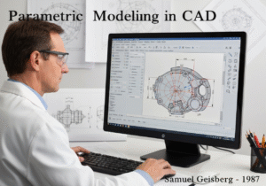
1987
1990
1990
1990
1980
1980
1986
1986
1987-03
1990
1990
1992


(如果日期不详或不相关,例如 "流体力学",则对其显著出现的时间作了四舍五入的估计)。
相关文章
METS 卡路里计算器
元分析
信息映射
心理模型图
可接受的最大推力和拉力
物料需求计划(MRP)