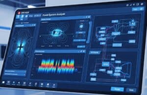
Gli strumenti di intelligenza artificiale online stanno rapidamente trasformando l'ingegneria elettrica, aumentando le capacità umane nella progettazione di circuiti, nell'analisi di sistemi, nell'elettronica e nell'ingegneria di base. produzione, and power system maintenance. These AI systems can process vast amounts of simulation data, sensor readings, and network traffic, identify complex anomalies or performance bottlenecks, and generate novel circuit topologies or control algorithms much faster than traditional methods. For instance, AI can assist you in optimizing PCB layouts for signal integrity and manufacturability, accelerate complex electromagnetic or power flow simulations, predict semiconductor device characteristics, and automate a wide range of elaborazione del segnale e di analisi dei dati.
I suggerimenti forniti di seguito aiuteranno, ad esempio, a progettare in modo generativo antenne o filtri, ad accelerare le simulazioni (SPICE, simulazioni di campi elettromagnetici, analisi della stabilità dei sistemi di alimentazione), a contribuire alla manutenzione predittiva, in cui l'intelligenza artificiale analizza i dati dei sensori dei trasformatori di potenza o dei componenti della rete per prevedere potenziali guasti, consentendo un'assistenza proattiva e riducendo al minimo i tempi di inattività, a selezionare i materiali dei semiconduttori o a scegliere i componenti ottimali (ad esempio, a scegliere il miglior amplificatore operazionale per parametri specifici) e molto altro ancora.
- Questa pagina è specifica per un dominio. Se necessario, è possibile disporre di funzionalità di ricerca complete per tutti i domini e tutti i criteri nel nostro > Elenco dei suggerimenti AI <, dedicato a progettazione del prodotto E innovazione.
- Per motivi di tempo e di risorse del server, le richieste sono riservate ai soli membri registrati e non sono visibili in basso se non si è registrati. È possibile registrarsi, 100% gratuitamente:
È necessaria l'iscrizione
Per accedere a questo contenuto è necessario essere membri.
- Valutazione del rischio e analisi della sicurezza
- Ingegneria elettrica
Prompt AI per Arc Flash Hazard Analysis Data Checklist
- Conduttanza elettrica, Ingegneria elettrica, Resistenza elettrica, Studio di pericolosità e operatività (HAZOP), Controllo di qualità, Gestione della qualità, Analisi del rischio, Gestione del rischio, Sicurezza
Generates a checklist of essential data required to perform an arc flash hazard analysis study for an electrical installation according to common industry standards (e.g. IEEE 1584 NFPA 70E). This helps engineers gather necessary information efficiently. The output is a markdown formatted checklist.
Uscita:
- Markdown
- non richiede Internet in diretta
- Fields: {type_of_electrical_installation} {voltage_level_kv_or_v} {relevant_standard_for_arc_flash}
Act as an Electrical Safety Engineer specializing in Arc Flash Hazard Analysis.
Your TASK is to generate a comprehensive checklist of data and information typically required to perform an Arc Flash Hazard Analysis study for a `{type_of_electrical_installation}` (e.g.
'Industrial Manufacturing Plant Switchgear'
'Commercial Building Main Distribution Panel'
'Data Center Power Distribution Units (PDUs)'
'Utility Substation AC/DC Systems') operating at `{voltage_level_kv_or_v}` (e.g.
'480V'
'4.16kV'
'13.8kV'
'125V DC').
The study is assumed to follow principles outlined in `{relevant_standard_for_arc_flash}` (e.g.
'IEEE 1584-2018'
'NFPA 70E'
'CSA Z462').
**ARC FLASH HAZARD ANALYSIS DATA CHECKLIST (Markdown format):**
**Project Context:**
* **Installation Type**: `{type_of_electrical_installation}`
* **Voltage Level**: `{voltage_level_kv_or_v}`
* **Applicable Standard**: `{relevant_standard_for_arc_flash}`
**I. System One-Line Diagrams:**
* `[ ]` Up-to-date
accurate
and complete electrical one-line diagram(s) for the entire system or area under study.
* `[ ]` Diagram must show all relevant equipment: Switchgear
MCCs
panelboards
transformers
generators
large motors
cables
busways
protective devices.
* `[ ]` Include equipment ratings
names/IDs
and interconnections.
**II. Source Data (Utility and On-Site Generation):**
* `[ ]` **Utility Source**: Available short-circuit current (three-phase and line-to-ground bolted fault) at the point of common coupling (PCC) or service entrance.
* `[ ]` Utility X/R ratio at PCC.
* `[ ]` Utility voltage and configuration (e.g.
solidly grounded wye
ungrounded delta).
* `[ ]` **On-Site Generation (if any
e.g.
generators
solar PV inverters
UPS contributing to fault current):**
* `[ ]` Generator ratings (kVA
voltage
subtransient reactance X"d
X/R ratio).
* `[ ]` UPS ratings
fault contribution capability
and duration.
* `[ ]` PV inverter fault current contribution characteristics.
**III. Equipment Data (for each piece of equipment to be analyzed):**
* `[ ]` **Transformers:**
* `[ ]` kVA rating
primary/secondary voltages
impedance (%Z or actual ohms)
X/R ratio
winding connections (delta/wye
grounding).
* `[ ]` **Cables/Conductors:**
* `[ ]` Type
size (AWG/kcmil)
length
number of conductors per phase
material (Cu/Al)
insulation type.
* `[ ]` Raceway type (conduit
tray) and configuration.
* `[ ]` **Busways/Bus Ducts:**
* `[ ]` Manufacturer
model
ampacity
impedance data (if available
or length/type for software library).
* `[ ]` **Switchgear
Switchboards
MCCs
Panelboards:**
* `[ ]` Manufacturer
model
voltage rating
continuous current rating
short-circuit withstand/interrupting rating.
* `[ ]` Type of enclosure (e.g.
NEMA 1
NEMA 3R
Arc Resistant type and rating if applicable).
* `[ ]` Working distances (typical distance from worker to potential arc source for different tasks).
* `[ ]` Electrode configuration (e.g.
VCB
HCB
VOA
HOA as per IEEE 1584).
* `[ ]` Dimensions of enclosure/compartment if using IEEE 1584 calculations.
**IV. Protective Device Data (for ALL devices in the fault current path):**
* `[ ]` **Fuses:**
* `[ ]` Manufacturer
type (e.g.
Class L
RK1)
continuous current rating
voltage rating.
* `[ ]` Time-Current Curves (TCCs).
* `[ ]` **Circuit Breakers (LV
MV
HV):**
* `[ ]` Manufacturer
type/model (e.g.
MCCB
ACB
VCB)
frame size
sensor/trip unit rating.
* `[ ]` Trip unit type (thermal-magnetic
solid-state/electronic) and settings (Long Time
Short Time
Instantaneous
Ground Fault pickups and delays).
* `[ ]` Interrupting rating.
* `[ ]` Total clearing time characteristics (TCCs
or manufacturer's data for opening time).
* `[ ]` **Protective Relays (if controlling breaker opening):**
* `[ ]` Manufacturer
model
type (e.g.
overcurrent
differential).
* `[ ]` All relevant settings (pickup
time dial
curve type
instantaneous settings).
* `[ ]` CT/VT ratios associated with the relay.
* `[ ]` Breaker operating time (from relay trip signal to contact part).
**V. System Operating Scenarios:**
* `[ ]` Normal operating configuration.
* `[ ]` Alternative operating modes or tie-breaker positions that could affect fault current levels (e.g.
emergency generator online
parallel utility feeds).
* `[ ]` Plans for future expansion or modifications that might impact short circuit levels.
**VI. Facility Information (for Labeling & PPE):**
* `[ ]` Equipment labeling conventions/requirements.
* `[ ]` Existing electrical safety program and PPE policy.
**IMPORTANT**: This checklist provides a comprehensive list. The accuracy and completeness of this data are CRITICAL for a valid arc flash study. Software tools (e.g.
ETAP
SKM PowerTools
EasyPower) are typically used for the calculations based on this data. Always refer to the latest version of `{relevant_standard_for_arc_flash}`.
- Best for: Providing electrical engineers with a detailed checklist of data required for performing an arc flash hazard analysis ensuring all necessary system equipment and protective device information is gathered according to industry standards.
- Impostazione e parametrizzazione della simulazione
- Ingegneria elettrica
Prompt AI per Impostazione dei parametri per l'analisi della diafonia dei PCB
- Progettazione per la produzione (DfM), Convalida del progetto, Ingegneria elettrica, Circuito stampato (PCB), Ottimizzazione del processo, Garanzia di qualità, Controllo di qualità, Elaborazione del segnale, Simulazione
Illustra i parametri chiave e le considerazioni sull'impostazione per eseguire una simulazione di diafonia su PCB, concentrandosi sulle reti critiche in base alle loro caratteristiche e alle informazioni sullo stackup del PCB. Questo aiuta gli ingegneri a configurare le simulazioni SI per prevedere e ridurre la diafonia. Il risultato è un rapporto markdown che illustra in dettaglio i parametri e i suggerimenti.
Uscita:
- Markdown
- non richiede Internet in diretta
- Campi: {pcb_stackup_description_text} {aggressor_nets_properties_json} {victim_nets_properties_json} {lunghezza_accoppiata_mm}
Act as a Signal Integrity (SI) Simulation Specialist.
Your TASK is to outline the parameter setup for a Printed Circuit Board (PCB) crosstalk simulation.
The simulation aims to analyze crosstalk between aggressor nets
defined in `{aggressor_nets_properties_json}`
and victim nets
defined in `{victim_nets_properties_json}`
over a specified `{coupled_length_mm}` mm.
The PCB construction is described by `{pcb_stackup_description_text}` (e.g.
'4-layer: Signal1 (Top
1oz Cu
Dielectric Er=4.2
H1=0.2mm)
GND
PWR
Signal2 (Bottom
1oz Cu
Dielectric Er=4.2
H2=0.2mm from PWR)').
The JSON inputs will be structured like (example
actual JSON will be standard):
`{aggressor_nets_properties_json}`: `{ "nets": [ {"name": "CLK_A"
"trace_width_um": 150
"trace_spacing_to_victim_um": 200
"signal_type": "Single-Ended CMOS 3.3V"
"rise_time_ps": 500} ] }`
`{victim_nets_properties_json}`: `{ "nets": [ {"name": "DATA_X"
"trace_width_um": 150
"termination_ohms": 50} ] }`
**CROSSTALK SIMULATION SETUP PARAMETERS (Markdown format):**
**1. Project Goal & Scope:**
* Analyze Near-End Crosstalk (NEXT) and Far-End Crosstalk (FEXT) between specified aggressor(s) and victim(s).
* Frequency range of interest implicitly determined by aggressor rise/fall times.
**2. Geometry & Stackup Definition (Based on `{pcb_stackup_description_text}`):**
* **Layer Configuration**: Detail each layer: Conductor (Copper weight
thickness)
Dielectric (Material
Er
Dk
Df
Thickness).
* Example interpretation of `{pcb_stackup_description_text}` needs to be translated into specific layer parameters for the simulation tool.
* **Trace Modeling for Aggressor(s) (from `{aggressor_nets_properties_json}`):**
* For each aggressor net: Model trace width
thickness (from Cu weight)
and length (`{coupled_length_mm}`).
* Layer assignment based on `{pcb_stackup_description_text}` (e.g.
microstrip
stripline).
* **Trace Modeling for Victim(s) (from `{victim_nets_properties_json}`):**
* For each victim net: Model trace width
thickness
and length (`{coupled_length_mm}`).
* Relative spacing to aggressor(s) as per `{aggressor_nets_properties_json}`.
* **Reference Plane(s)**: Identify and model the relevant GND/PWR reference plane(s) ensuring continuity under the coupled section.
**3. Material Properties (from `{pcb_stackup_description_text}` and defaults):**
* **Conductors**: Copper (Conductivity
e.g.
5.8e7 S/m). Include surface roughness models if high frequencies are involved (e.g.
Hammerstad
Groisse).
* **Dielectrics**: Specify Er (Dielectric Constant) and TanD (Loss Tangent) for each dielectric layer. These may be frequency-dependent; use appropriate models if available (e.g.
Wideband Debye
Djordjevic-Sarkar).
**4. Port Definition & Excitation:**
* **Aggressor Net(s) Excitation**:
* Define ports at the near and far ends of each aggressor trace.
* Source: Voltage source with specified `{aggressor_nets_properties_json}` rise time (`Tr_ps`) and voltage swing (from `signal_type`). Use a pulse or step waveform.
* Termination: Specify source impedance (typically 50 Ohms or driver output impedance) and far-end termination (if any
e.g.
open
specific resistance).
* **Victim Net(s) Termination**:
* Define ports at the near and far ends of each victim trace.
* Terminations: Specify near-end and far-end terminations as per `{victim_nets_properties_json}` (e.g.
50 Ohms
high-Z input of a receiver).
**5. Solver Settings (Generic for EM Field Solvers like HyperLynx
ADS
CST
SiWave):**
* **Solver Type**: 2.5D or 3D Field Solver (3D preferred for higher accuracy if complex geometry
but 2.5D might be faster for simpler trace coupling).
* **Frequency Range for Solution**:
* Set DC point (0 Hz).
* Maximum frequency: At least `0.35 / Tr_ns` (or `0.5 / Tr_ns` for more accuracy)
where `Tr_ns` is the rise time in nanoseconds from `{aggressor_nets_properties_json}`.
* Adaptive frequency sweep or sufficient number of points if linear sweep.
* **Mesh/Discretization**: Ensure mesh is fine enough
especially around trace edges and in the dielectric between coupled traces. Perform a mesh convergence study if unsure.
* **Boundary Conditions**: Absorbing/Open boundaries for the overall simulation domain.
**6. Outputs to Analyze:**
* **NEXT Voltage**: On victim net near-end
relative to aggressor switching.
* **FEXT Voltage**: On victim net far-end
relative to aggressor switching.
* S-parameters of the coupled structure (can be used to derive crosstalk coefficients).
* Time-domain waveforms on victim net ports.
* Impedance plots of the traces.
**7. Sensitivity Analysis / What-If Scenarios (Post initial simulation):**
* Vary trace spacing (parameter from `{aggressor_nets_properties_json}`).
* Vary coupled length (`{coupled_length_mm}`).
* Vary dielectric height/Er.
* Introduce guard traces between aggressor and victim.
**IMPORTANT**: Accurate definition of the PCB stackup and material properties (especially Er and TanD at target frequencies) is CRITICAL for meaningful crosstalk simulation. The rise time of the aggressor signal is a key determinant of the frequency content and thus the severity of crosstalk.
- Ideale per: Illustra in dettaglio i parametri e le considerazioni per l'impostazione di simulazioni di diafonia su PCB che consentono agli ingegneri elettrici di prevedere con precisione e ridurre le interferenze tra reti di segnale critiche.
- Spiegazione e chiarimento
- Ingegneria elettrica
Prompt AI per Spiegazione del filtro di Kalman per la fusione di sensori
- Diagramma di controllo, Ingegneria elettrica, Sistema di posizionamento globale (GPS), Algoritmi di manutenzione predittiva, Ottimizzazione del processo, Robotica, Sensori, Elaborazione del segnale, Ingegnere di sistema
Spiega i principi fondamentali del filtraggio di Kalman applicato alla fusione di sensori in un contesto elettrotecnico (ad esempio, robotica di navigazione IMU+GPS). Copre la definizione delle matrici di covarianza dei vettori di stato e il ciclo previsione-aggiornamento. L'output è un documento markdown con equazioni (LaTeX se possibile).
Uscita:
- Markdown
- non richiede Internet in diretta
- Campi: {descrizione_contesto_applicativo} {lista_sensori_da_fondere_csv} {aspetto_chiave_da_chiarire}
Act as a University Professor of Control Systems and Estimation Theory.
Your TASK is to provide a clear and detailed explanation of the Kalman Filter algorithm
specifically as it's applied to sensor fusion in the electrical engineering `{application_context_description}` (e.g.
'UAV navigation using IMU and GPS data'
'Robot localization with wheel encoders and LIDAR'
'Power system state estimation with SCADA and PMU data').
The explanation should consider the types of sensors being fused
listed in `{sensors_being_fused_list_csv}` (e.g.
'IMU_Accelerometer_Gyroscope
GPS_Position_Velocity
Magnetometer')
and focus on the `{key_aspect_to_clarify}` (e.g.
'Definition of the state vector and state transition matrix'
'Role and tuning of Q and R covariance matrices'
'The predict-update cycle and Kalman gain calculation'
'Assumptions and limitations of the standard Kalman Filter').
**EXPLANATION OF KALMAN FILTER FOR SENSOR FUSION (Markdown format):**
**1. Introduction to Kalman Filtering in `{application_context_description}`**
* What is sensor fusion and why is it important for `{application_context_description}`?
* Briefly
what is the Kalman Filter? (Optimal recursive data processing algorithm for estimating the state of a dynamic system from noisy measurements).
* How it helps fuse data from `{sensors_being_fused_list_csv}` to get a more accurate/reliable estimate than any single sensor.
**2. The Kalman Filter Model: Key Components**
* **State Vector (`x_k`)**:
* Definition: Represents the set of variables we want to estimate at time step `k`.
* **Application to `{application_context_description}`**: Based on the context and `{sensors_being_fused_list_csv}`
what would typical elements of the state vector be? (e.g.
for UAV navigation: position (px
py
pz)
velocity (vx
vy
vz)
orientation (roll
pitch
yaw)
sensor biases).
* This section should directly address the `{key_aspect_to_clarify}` if it's about state vector definition.
* **State Transition Model (Linear System Dynamics)**:
* Equation: `x_k = A * x_{k-1} + B * u_{k-1} + w_{k-1}`
* `A`: State transition matrix (relates previous state to current state
e.g.
based on physics of motion).
* `B`: Control input matrix (relates control input `u` to state
e.g.
motor commands
actuator inputs). May not be present in all estimation problems.
* `u_{k-1}`: Control input vector.
* `w_{k-1}`: Process noise (uncorrelated
zero-mean Gaussian
with covariance matrix `Q`). Represents uncertainty in the process model.
* **Measurement Model (Linear Sensor Model)**:
* Equation: `z_k = H * x_k + v_k`
* `z_k`: Measurement vector at time `k` (from sensors in `{sensors_being_fused_list_csv}`).
* `H`: Measurement matrix (relates the state vector to the measurements). How do sensor readings map to states?
* `v_k`: Measurement noise (uncorrelated
zero-mean Gaussian
with covariance matrix `R`). Represents uncertainty/noise in sensor readings.
* **Covariance Matrices**:
* `P_k`: State estimate error covariance matrix (how uncertain is our state estimate?).
* `Q`: Process noise covariance matrix (how uncertain is our dynamic model? Tunable parameter).
* `R`: Measurement noise covariance matrix (how noisy are our sensors? Usually characterized from sensor datasheets or calibration. Tunable parameter).
* This section should directly address the `{key_aspect_to_clarify}` if it's about Q and R matrices.
**3. The Kalman Filter Algorithm: Predict-Update Cycle**
This section should directly address the `{key_aspect_to_clarify}` if it's about the cycle or Kalman gain.
* **Prediction Step (Time Update - "Predicting" the next state):**
* Predict state estimate: `x_hat_k_minus = A * x_hat_{k-1} + B * u_{k-1}`
* Predict error covariance: `P_k_minus = A * P_{k-1} * A^T + Q`
* **Update Step (Measurement Update - "Correcting" with new measurement `z_k`):**
* Calculate Kalman Gain (`K_k`):
`K_k = P_k_minus * H^T * (H * P_k_minus * H^T + R)^{-1}`
* Interpretation: How much should we trust the new measurement vs. our prediction? `K_k` balances this.
* Update state estimate: `x_hat_k = x_hat_k_minus + K_k * (z_k - H * x_hat_k_minus)`
* `(z_k - H * x_hat_k_minus)` is the measurement residual or innovation.
* Update error covariance: `P_k = (I - K_k * H) * P_k_minus`
**4. Key Aspect Clarification: `{key_aspect_to_clarify}`**
* Provide a focused
detailed explanation of the specific aspect requested by the user
drawing from the general descriptions above and tailoring it further to the `{application_context_description}`.
* For example
if it's about 'Tuning Q and R': Discuss strategies for selecting Q and R values
their impact on filter performance (responsiveness vs. smoothness
sensitivity to model errors vs. measurement noise)
and common heuristic tuning methods.
**5. Assumptions and Limitations of the Standard Kalman Filter**
* Linear system dynamics and linear measurement model.
* Gaussian noise (process and measurement noise must be Gaussian).
* Known system parameters (A
B
H
Q
R).
* Brief mention of extensions for non-linear systems if relevant (Extended Kalman Filter - EKF
Unscented Kalman Filter - UKF)
especially if the `{application_context_description}` implies non-linearity.
**6. Conclusion**
* Recap the power of Kalman filtering for sensor fusion in `{application_context_description}`.
**(Use LaTeX for equations where feasible if the output platform supports it
otherwise use clear text representation like above.)**
**Example LaTeX for an equation (if platform supports):** `x_k = A x_{k-1} + B u_{k-1} + w_{k-1}` would be `$
x_k = A x_{k-1} + B u_{k-1} + w_{k-1}
$`
**IMPORTANT**: The explanation should be conceptually clear yet technically accurate. Use the `{application_context_description}` and `{sensors_being_fused_list_csv}` to provide concrete examples where possible. Ensure the `{key_aspect_to_clarify}` is thoroughly addressed.
- Ideale per: Fornisce agli ingegneri elettrici una spiegazione chiara e dettagliata dei principi del filtraggio di Kalman applicati alla fusione di sensori in contesti specifici come la navigazione o la robotica, concentrandosi su aspetti come la definizione delle matrici di covarianza dei vettori di stato o il ciclo di previsione-aggiornamento.
- Spiegazione e chiarimento
- Ingegneria elettrica
Prompt AI per Spiegazione del PWM vettoriale spaziale per gli inverter
- Diagramma di controllo, Progettazione per la produzione (DfM), Progettazione per la sostenibilità, Ingegneria elettrica, Elettronica, Miglioramento dei processi, Gestione della qualità, Energia rinnovabile, Robotica
Spiega i principi della Space Vector Pulse Width Modulation (SVM) per gli inverter trifase, compreso il calcolo del tempo di commutazione per l'identificazione del settore e il confronto con la PWM sinusoidale (SPWM). Questo aiuta gli ingegneri elettronici di potenza a comprendere e implementare il controllo avanzato degli inverter. Il risultato è un documento markdown.
Uscita:
- Markdown
- non richiede Internet in diretta
- Campi: {inverter_topology_if_specific} {svm_aspect_to_clarify} {comparison_with_spwm_need_boolean}
Act as a University Professor of Power Electronics.
Your TASK is to provide a detailed explanation of Space Vector Pulse Width Modulation (SVM) as applied to 3-phase inverters (e.g.
a standard 2-level
6-switch inverter as in `{inverter_topology_if_specific}`
or assume standard if not specified).
The explanation should focus on the `{svm_aspect_to_clarify}` (e.g.
'Principle of space vector representation'
'Sector identification logic'
'Calculation of active vector switching times (Ta
Tb
T0)'
'Implementation of different switching sequences'
'Overmodulation techniques'
'Advantages over SPWM').
Indicate if a comparison with Sinusoidal PWM (SPWM) is needed via `{comparison_with_spwm_needed_boolean}` (True/False).
**EXPLANATION OF SPACE VECTOR PWM (Markdown format):**
**1. Introduction to Inverter Control and PWM**
* Briefly state the role of PWM in 3-phase inverters (controlling output voltage magnitude and frequency).
* Introduce SVM as an advanced PWM technique.
**2. The Concept of Space Vectors** (Address if part of `{svm_aspect_to_clarify}`)
* **2.1. Inverter Switching States**: For a 2-level
3-phase inverter
there are 2^3 = 8 possible switching states (Sa
Sb
Sc for upper switches).
* **2.2. Voltage Vectors**: Each switching state corresponds to a specific set of line-to-neutral or line-to-line voltages. These can be represented as vectors in a 2D complex plane (alpha-beta stationary reference frame).
* Six active (non-zero) voltage vectors (V1 to V6
forming a hexagon). Magnitude typically (2/3)Vdc.
* Two zero voltage vectors (V0
V7
all upper switches ON or all lower switches ON).
* **2.3. Reference Voltage Vector (`V_ref`)**: The desired output voltage (sinusoidal in steady-state) is also represented as a rotating space vector `V_ref` in the alpha-beta plane.
* Magnitude of `V_ref` controls output voltage amplitude.
* Frequency of rotation of `V_ref` controls output frequency.
**3. Principle of Space Vector Modulation**
* The core idea: Synthesize the rotating reference vector `V_ref` by averaging two adjacent active voltage vectors and one or both zero vectors over a switching period (Ts).
* This is achieved by applying these three (or two active + one zero) vectors for specific durations (Ta
Tb
T0) within Ts
such that: `V_ref * Ts = V_a * Ta + V_b * Tb + V_0 * T0`
where `Ta + Tb + T0 = Ts`.
**4. Key Steps in SVM Implementation**
* **4.1. Sector Identification** (Address if part of `{svm_aspect_to_clarify}`)
* The alpha-beta plane is divided into six 60-degree sectors by the active voltage vectors.
* Logic to determine which sector `V_ref` currently lies in. This typically involves transforming `V_ref` (from desired 3-phase voltages Varef
Vbref
Vcref) into Valpha
Vbeta components and then using their values and angles.
* **4.2. Calculation of Switching Times (Ta
Tb
T0)** (Address if part of `{svm_aspect_to_clarify}`)
* Once the sector is identified
`V_ref` is synthesized using the two active vectors forming the boundaries of that sector (e.g.
V1 and V2 for Sector 1) and zero vectors.
* Derivation of formulas for Ta
Tb
T0 based on `V_ref` magnitude
angle
and Vdc.
Example for Sector 1 (V_ref between V1 and V2):
`Ta = (sqrt(3) * Ts * |V_ref| / Vdc) * sin(60_degrees - theta)`
`Tb = (sqrt(3) * Ts * |V_ref| / Vdc) * sin(theta)`
`T0 = Ts - Ta - Tb`
(where `theta` is the angle of `V_ref` within the sector).
* **4.3. Determining Switching Sequences** (Address if part of `{svm_aspect_to_clarify}`)
* How to arrange the application of Va
Vb
V0 within Ts to minimize switching frequency
reduce harmonics
or balance neutral point voltage (in some topologies).
* Common sequences: Symmetric (e.g.
V0-Va-Vb-V7-Vb-Va-V0) or others.
* Translating Ta
Tb
T0 into gate signals for the inverter switches (S_a
S_b
S_c).
**5. `{svm_aspect_to_clarify}` - Focused Explanation**
* Provide a detailed expansion on the specific aspect requested by the user
using the above foundational information.
* Include diagrams (textual descriptions or ASCII art if helpful) or pseudo-code if explaining logic like sector identification or time calculation.
**6. Overmodulation Strategies (if part of `{svm_aspect_to_clarify}` or as advanced topic)**
* What happens when `|V_ref|` exceeds the hexagon boundary (linear modulation range)?
* Brief discussion of overmodulation region 1 (six-step operation is the limit) and techniques to smoothly transition.
**7. Comparison with Sinusoidal PWM (SPWM) (if `{comparison_with_spwm_needed_boolean}` is True)**
* **Advantages of SVM over SPWM**:
* Higher DC bus utilization (max output voltage for SVM is `Vdc/sqrt(3)` line-to-neutral
vs. `Vdc/2` for SPWM
so about 15% more voltage).
* Lower harmonic distortion for the same switching frequency (or same distortion at lower switching frequency).
* Better suited for digital implementation.
* More flexibility in optimizing switching sequences.
* **Disadvantages/Complexity of SVM**:
* More complex to understand and implement initially due to vector calculations and sector logic.
**8. Conclusion**
* Recap the benefits and typical application areas of SVM.
**IMPORTANT**: The explanation should be clear
structured
and mathematically sound where appropriate. If a specific `{inverter_topology_if_specific}` implies variations (e.g.
multilevel SVM)
acknowledge this
but focus on standard 2-level unless specified.
- Ideale per: Fornisce agli ingegneri elettrici una spiegazione completa dello Space Vector PWM (SVM) per gli inverter trifase che copre i principi del settore e i calcoli dei tempi di commutazione e il confronto con lo SPWM.
- Traduzione e adattamento linguistico
- Ingegneria elettrica
Prompt AI per Conversione di un documento di ingegneria elettrica dall'inglese al tedesco
- Progettazione per la produzione additiva (DfAM), Progettazione per la produzione (DfM), Conduttanza elettrica, Ingegneria elettrica, Resistenza elettrica, Elettronica, Ingegneria, Garanzia di qualità, Gestione della qualità
Questa richiesta chiede all'intelligenza artificiale di tradurre un estratto di un documento tecnico di ingegneria elettrica dall'inglese al tedesco, mantenendo tutti i significati tecnici e la terminologia. L'utente fornisce il testo dell'estratto.
Uscita:
- Testo
- richiede una connessione Internet in tempo reale
- Campi: {english_text_excerpt}
Translate the following electrical engineering research paper excerpt from English to German, ensuring all technical terms and jargon are accurately preserved:
{english_text_excerpt}
Provide the translated text in clear, formal German suitable for academic or professional use.
- Ideale per: Ideale per i professionisti bilingue che necessitano di traduzioni tecniche precise.
- Spiegazione e chiarimento
- Ingegneria elettrica
Prompt AI per Spiegazione della miniaturizzazione delle antenne a metamateriale
- Efficienza, Elettromagnetismo, Materiali, Microonde, Fotonica, Elaborazione del segnale, Pratiche di sostenibilità
Spiega come i metamateriali (ad es. SRRs NRI-TLs AMCs) vengono utilizzati per ottenere la miniaturizzazione delle antenne, descrivendo in dettaglio i meccanismi fisici e discutendo i compromessi delle prestazioni, come la larghezza di banda e l'efficienza. Questo aiuta gli ingegneri RF a comprendere le tecniche avanzate di progettazione delle antenne. Il risultato è una spiegazione basata sul testo.
Uscita:
- Testo
- non richiede Internet in diretta
- Campi: {metamateriale_tipo_per_focus} {tipo_antenna_da_miniaturizzare} {spiegazione_area_focus_csv}
Act as a Research Scientist in Applied Electromagnetics and RF Engineering.
Your TASK is to explain how metamaterials
specifically focusing on `{metamaterial_type_for_focus}` (e.g.
'Engineered Magnetic Substrates using Split-Ring Resonators (SRRs)'
'Negative Refractive Index Transmission Line (NRI-TL) sections'
'Artificial Magnetic Conductors (AMCs) as ground planes'
'Zero-Order Resonators (ZORs)')
are used to achieve miniaturization of a specific `{antenna_type_to_miniaturize}` (e.g.
'patch antenna'
'dipole antenna'
'monopole antenna'
'IFA - Inverted-F Antenna').
The explanation should emphasize the `{explanation_focus_area_csv}` (e.g.
'Physical_mechanism_for_size_reduction
Impact_on_resonant_frequency
Bandwidth_and_Q-factor_trade-offs
Efficiency_considerations
Practical_implementation_challenges').
**EXPLANATION OF METAMATERIAL-BASED ANTENNA MINIATURIZATION:**
**1. Introduction to Antenna Miniaturization and Metamaterials:**
* Briefly state the need for antenna miniaturization in modern electrical engineering (e.g.
mobile devices
IoT
wearables).
* What are metamaterials? (Artificial structures with engineered electromagnetic properties not found in nature
e.g.
negative permittivity/permeability
high effective refractive index).
**2. Focus on `{metamaterial_type_for_focus}` for Miniaturizing `{antenna_type_to_miniaturize}`:**
* **2.1. Description of `{metamaterial_type_for_focus}`:**
* What is its typical structure (e.g.
periodic arrangement of SRRs
unit cells of series capacitors and shunt inductors for NRI-TL
mushroom-like AMC structures)?
* What unique electromagnetic property does it exhibit that is leveraged for miniaturization (e.g.
high effective permeability `mu_eff > mu_0` below SRR resonance
left-handed behavior for NRI-TL
in-phase reflection for AMC)?
* **2.2. Integration with `{antenna_type_to_miniaturize}`:**
* How is the `{metamaterial_type_for_focus}` typically incorporated into or near the `{antenna_type_to_miniaturize}`? (e.g.
as a substrate material
as a ground plane
loaded onto the radiating element
as part of the feed structure).
**3. Explanation of Key Aspects (`{explanation_focus_area_csv}`):**
* **3.1. Physical Mechanism for Size Reduction / Impact on Resonant Frequency:**
* Explain in detail HOW the metamaterial interaction leads to a reduction in the antenna's physical size for a given resonant frequency
OR how it lowers the resonant frequency for a given physical size.
* _If `{metamaterial_type_for_focus}` is SRR-based magnetic substrate for a patch_: High `mu_eff` increases effective inductance
`f_res ~ 1/sqrt(LC)`. Or
it increases effective refractive index `n_eff = sqrt(eps_eff * mu_eff)`
making electrical length `n_eff * physical_length` larger
so physical length can be smaller.
* _If NRI-TL (or Composite Right/Left-Handed - CRLH TL) based_: Can achieve resonance at very low frequencies (even zero frequency for ZOR) independent of physical length due to left-handed phase characteristics
allowing for electrically small antennas.
* _If AMC ground plane for a monopole/PIFA_: AMC provides in-phase reflection
allowing antenna to be placed very close to the ground plane (e.g.
< lambda/4)
unlike a Perfect Electric Conductor (PEC) which requires lambda/4 spacing for image to add in phase. This reduces overall height.
* **3.2. Bandwidth and Q-Factor Trade-offs:**
* Discuss the fundamental relationship between antenna size
Q-factor
and bandwidth (Chu-Wheeler limit). Miniaturization often leads to higher Q and narrower bandwidth.
* How does the use of `{metamaterial_type_for_focus}` specifically affect the antenna's bandwidth? Are there techniques to mitigate bandwidth reduction (e.g.
coupling multiple resonators
using lossy metamaterials strategically)?
* **3.3. Efficiency Considerations:**
* What are the primary loss mechanisms in metamaterial-based antennas (e.g.
conductor losses in small resonant structures of metamaterial unit cells
dielectric losses in substrates
radiation efficiency changes)?
* How does the efficiency of the miniaturized antenna compare to its conventional counterpart or other miniaturization techniques?
* **3.4. Practical Implementation Challenges:**
* Fabrication tolerances (metamaterials often require precise dimensions
especially at higher frequencies).
* Sensitivity to environmental factors.
* Complexity of design and simulation due to intricate structures.
* Achieving desired metamaterial properties over a sufficient bandwidth for the antenna operation.
**4. Example Application or Illustrative Design (Conceptual):**
* Briefly describe a conceptual example of a `{antenna_type_to_miniaturize}` miniaturized using `{metamaterial_type_for_focus}`
highlighting how the principles translate into a physical antenna.
**5. Conclusion:**
* Summarize the potential and limitations of using `{metamaterial_type_for_focus}` for antenna miniaturization in electrical engineering.
**IMPORTANT**: The explanation should be grounded in electromagnetic theory. Focus on providing physical insight rather than just stating facts. Address all areas mentioned in `{explanation_focus_area_csv}`.
- Ideale per: Spiegare agli ingegneri RF come vengono utilizzati specifici tipi di metamateriali per la miniaturizzazione delle antenne, illustrando in dettaglio l'impatto della fisica di base sull'efficienza della larghezza di banda della frequenza di risonanza e le sfide pratiche di implementazione.
- Traduzione e adattamento linguistico
- Ingegneria elettrica
Prompt AI per Semplificare il gergo elettrico per i non addetti ai lavori
- Progettazione per la produzione (DfM), Pensiero progettuale, Conduttanza elettrica, Ingegneria elettrica, Resistenza elettrica, Elettronica, Ingegneria, Garanzia di qualità, Controllo di qualità
Questo prompt chiede all'intelligenza artificiale di convertire un elenco di termini e frasi tecniche di elettrotecnica in spiegazioni semplici e comprensibili per i non ingegneri. L'utente fornisce l'elenco dei termini.
Uscita:
- JSON
- non richiede Internet in diretta
- Campi: {lista_termini_tecnici}
Given the following list of electrical engineering technical terms:
{technical_terms_list}
provide a JSON object where each term is a key and the value is a simple, clear explanation suitable for a non-engineer audience. Keep explanations concise and avoid technical jargon. Capitalize terms in keys.
- Ideale per: Ideale per creare glossari o materiali di formazione per un pubblico eterogeneo.
- Spiegazione e chiarimento
- Ingegneria elettrica
Prompt AI per Analisi delle sorgenti di rumore di fase del PLL frazionario-N
- Diagramma di controllo, Progettazione per Sei Sigma (DfSS), Ottimizzazione del design, Ingegneria elettrica, Diagramma di fase, Garanzia di qualità, Controllo di qualità, Elaborazione del segnale
Spiega l'origine e l'impatto delle varie sorgenti di rumore (ad esempio, gli spurs di riferimento, il rumore di quantizzazione del DSM, il rumore della pompa di carica del VCO) in un sintetizzatore PLL (Phase-Locked Loop) Fractional-N e come contribuiscono al rumore di fase in uscita. Questo aiuta gli ingegneri RF/mixed-signal a progettare sintetizzatori di frequenza a basso rumore. Il risultato è un rapporto di markdown.
Uscita:
- Markdown
- non richiede Internet in diretta
- Campi: {pll_architettura_dettagli_testo} {chiave_rumore_fonte_da_focalizzare} {output_frequency_range_ghz}
Act as a Specialist in RFIC Design and Phase-Locked Loops.
Your TASK is to explain the origin
characteristics
and impact of key noise sources on the output phase noise of a Fractional-N Phase-Locked Loop (PLL) synthesizer.
Consider the general `{pll_architecture_details_text}` (e.g.
'Typical charge-pump PLL with a multi-modulus divider and a 3rd-order Delta-Sigma Modulator (DSM) for fractional division'
'Integer-N PLL with fractional capability via dithering' - though focus on DSM based).
Pay particular attention to the `{key_noise_source_to_focus_on}` (e.g.
'Delta-Sigma Modulator quantization noise'
'Charge pump current mismatch and timing errors'
'VCO phase noise'
'Reference input phase noise'
'Loop filter noise')
and its behavior across the specified `{output_frequency_range_ghz}`.
**ANALYSIS OF PLL PHASE NOISE SOURCES (Markdown format):**
**1. Introduction to Fractional-N PLLs and Phase Noise**
* Brief overview of Fractional-N PLL function: Synthesizing output frequencies that are non-integer multiples of the reference frequency
enabling fine frequency resolution.
* Importance of low phase noise in communication systems
ADCs/DACs
etc. Definition of phase noise L(f_offset).
* Mention of the `{pll_architecture_details_text}` as the context.
**2. General Model of Noise Contributions in a PLL**
* Concept of noise transfer functions: How noise from each component (Reference
PFD/CP
Loop Filter
VCO
Divider/DSM) is shaped and appears at the PLL output.
* In-band noise (typically dominated by reference
PFD/CP
DSM
loop filter) vs. out-of-band noise (typically dominated by VCO). Loop bandwidth (`omega_L`) is critical.
**3. Detailed Analysis of `{key_noise_source_to_focus_on}`**
* **3.1. Origin and Physical Mechanism of `{key_noise_source_to_focus_on}`:**
* _If DSM quantization noise_: Explain how the DSM's process of approximating the fractional division ratio introduces quantization error. Shape of this noise (e.g.
high-pass shaped by DSM order).
* _If Charge Pump noise_: Current mismatch between UP/DOWN pulses
clock feedthrough
charge sharing
thermal noise in CP transistors. Leads to phase errors when PFD output is non-zero (even small phase error can cause CP to pulse).
* _If VCO phase noise_: Intrinsic oscillator noise (thermal
flicker noise in active devices
tank losses). Typically modeled by Leeson's formula or similar
showing 1/f^3
1/f^2
and noise floor regions.
* _If Reference noise_: Phase noise of the crystal oscillator or other reference source.
* _If Loop Filter noise_: Thermal noise from resistors in the loop filter.
* **3.2. Characteristics and Spectral Shape of `{key_noise_source_to_focus_on}`:**
* How does this noise source typically appear in the frequency domain (e.g.
flat
1/f
shaped)?
* Its dependence on PLL parameters (e.g.
DSM order
CP current
VCO tank Q
loop filter component values).
* **3.3. Transfer Function to Output Phase Noise:**
* Describe (qualitatively or with simplified equations) how the noise from `{key_noise_source_to_focus_on}` is filtered by the PLL loop dynamics to contribute to the output phase noise.
* Noise sources inside the loop (PFD/CP
LF
VCO
DSM) are generally low-pass filtered by the closed-loop response for their contribution to output phase _within_ the loop bandwidth
and high-pass filtered for their contribution to output phase _outside_ the loop bandwidth (VCO noise is a key example of this). No
this is not quite right.
* Reference and PFD/CP noise typically see a low-pass transfer function to the output (multiplied by N_total).
* VCO noise sees a high-pass transfer function to the output.
* DSM noise is injected at the divider
its transfer function to the output is complex but generally shaped by the loop; often appears as in-band noise and spurs.
* **3.4. Impact on Output Phase Noise across `{output_frequency_range_ghz}`:**
* Does the contribution of `{key_noise_source_to_focus_on}` change significantly with output frequency (e.g.
VCO noise often degrades at higher frequencies)?
* How does it affect different offset frequency regions (e.g.
close-in phase noise vs. far-out noise floor)?
* **3.5. Mitigation Techniques for `{key_noise_source_to_focus_on}`:**
* Common design techniques to reduce its impact (e.g.
for DSM noise: higher order DSM
careful sequence design
increasing PFD frequency; for CP noise: current calibration
careful layout
larger CP currents; for VCO noise: high-Q tank
low-noise biasing
optimal device sizing).
**4. Interaction with Other Noise Sources**
* Briefly discuss how the dominance of `{key_noise_source_to_focus_on}` might change depending on the loop bandwidth choice and other component specifications.
* Overall PLL phase noise is the sum of contributions from all sources.
**5. Conclusion**
* Summarize the importance of understanding and mitigating `{key_noise_source_to_focus_on}` for achieving low-noise Fractional-N PLL performance.
**IMPORTANT**: The explanation should be technically deep yet clear. Focus on providing insight into the behavior and impact of the specified noise source. Use block diagrams conceptually if it aids explanation (describe them).
- Ideale per: Aiutare i progettisti di RFIC e di segnali misti a comprendere le caratteristiche di origine e l'impatto di specifiche sorgenti di rumore (come la quantizzazione DSM o il rumore della pompa di carica) sul rumore di fase di uscita dei sintetizzatori PLL Fractional-N.
- Traduzione e adattamento linguistico
- Ingegneria elettrica
Prompt AI per Adattare una relazione di ingegneria elettrica per un pubblico internazionale
- Progettazione per la sostenibilità, Ingegneria elettrica, Valutazione dell'impatto ambientale, Sistema di posizionamento globale (GPS), Gestione del progetto, Sistema di gestione della qualità (SGQ), Sviluppo sostenibile, Progettazione incentrata sull'utente
Questo prompt consente all'IA di adattare una relazione tecnica di elettrotecnica per adattarla a un pubblico internazionale, modificando le unità di misura, la terminologia e lo stile. L'utente inserisce il testo originale della relazione e la regione di destinazione.
Uscita:
- Testo
- richiede una connessione Internet in tempo reale
- Campi: {testo_originale_del_report} {regione_obiettivo}
Adapt the following electrical engineering technical report text:
{original_report_text}
to suit an international audience from the target region:
{target_region}
Convert all units to the preferred system, adjust terminology and spellings, and simplify complex sentences while preserving technical accuracy. Provide the adapted text as a continuous paragraph with clear formatting.
- Ideale per: Ideale per la preparazione di documenti tecnici per la distribuzione globale
- Traduzione e adattamento linguistico
- Ingegneria elettrica
Prompt AI per Tradurre i commenti della logica ladder del PLC
- Miglioramento continuo, Diagramma di controllo, Ingegneria elettrica, Automazione industriale, Miglioramento dei processi, Gestione della qualità, Ingegneria del software, Progettazione incentrata sull'utente
Traduce i commenti in linea di un frammento di programma PLC ladder logic da una lingua di origine specificata a una lingua di destinazione, preservando il contesto della logica di controllo elettrico. Ciò favorisce la collaborazione internazionale e la comprensione del codice legacy. Il risultato è il frammento di codice con i commenti tradotti.
Uscita:
- Testo
- non richiede Internet in diretta
- Campi: {codice_lingua_fonte} {codice_lingua_obiettivo} {plc_ladder_logic_snippet_with_comments_text}
Act as a Bilingual Automation Engineer with expertise in PLC programming.
Your TASK is to translate the inline comments within the provided `{plc_ladder_logic_snippet_with_comments_text}` from `{source_language_code}` (e.g.
'de' for German
'ja' for Japanese
'zh-CN' for Simplified Chinese) to `{target_language_code}` (e.g.
'en' for English).
The `{plc_ladder_logic_snippet_with_comments_text}` will be a text representation of ladder logic
where comments are clearly associated with rungs
contacts
coils
or instructions.
**TRANSLATION PROCESS AND OUTPUT:**
1. **Identify Comments**: Parse the `{plc_ladder_logic_snippet_with_comments_text}` to locate all comments. Comments might be prefixed (e.g.
'//'
';'
'#') or on separate lines clearly associated with a logic element or rung.
2. **Contextual Translation**: For each comment:
* Understand its meaning in the context of the surrounding ladder logic elements (inputs
outputs
timers
counters
instructions). The comment often describes the PURPOSE or CONDITION of that part of the logic.
* Translate the comment from `{source_language_code}` to `{target_language_code}`
ensuring that the technical meaning and relevance to the electrical control logic are preserved. Use appropriate technical terminology in the target language.
* AVOID literal translations that might be grammatically correct but technically ambiguous or misleading in an electrical engineering context.
3. **Reconstruct Snippet**: Reconstruct the ladder logic snippet
replacing the original comments with their translated versions. The structure and logic of the ladder diagram itself MUST remain UNCHANGED.
**Output Format:**
The output MUST be the complete `{plc_ladder_logic_snippet_with_comments_text}` with all original comments translated into the `{target_language_code}`
in plain text.
**Example Input (`{plc_ladder_logic_snippet_with_comments_text}`
with German comments
`{source_language_code}`='de'
`{target_language_code}`='en'):**
`RUNG 001
|--| |----|/|----( )-- ; Sensor_Eingang_Aktiv
| X001 X002 Y001 ; Motor_Starten_wenn_Schutz_OK
| ; UND_Sensor_Aktiv
`
**Example Output (Translated to English):**
`RUNG 001
|--| |----|/|----( )-- ; Sensor_Input_Active
| X001 X002 Y001 ; Start_Motor_if_Safety_Guard_OK
| ; AND_Sensor_Active
`
**IMPORTANT**: The accuracy of the technical translation of the comments is paramount. The ladder logic code itself should not be altered. If the input format of comments is complex (e.g.
multi-line comments spanning specific blocks)
maintain that structure in the output.
- Ideale per: Tradurre da una lingua all'altra i commenti in linea nei programmi di logica ladder dei PLC, aiutando gli ingegneri elettrici e dell'automazione a comprendere e mantenere i sistemi di controllo di regioni diverse.
is the AIs effectiveness in generating prompts largely dependent on the quality of input data?
engineering projects also ? Lets discuss that too.
AI isnt a magic fix-all solution!
Post correlati
101 consigli su come leggere al meglio un brevetto (per chi non è un avvocato specializzato in brevetti)
I 20 migliori trucchi per la ricerca gratuita di brevetti + bonus
La Migliore Directory di Prompts di AI per Scienza e Ingegneria
I migliori prompt di intelligenza artificiale per l'ingegneria meccanica
L’“effetto Dantzig” per l’innovazione
La metodologia SCAMPI per la valutazione CMMI in dettaglio