Apoyar la especificación, el análisis, el diseño, verificación, y validación de una amplia gama de sistemas y sistemas de sistemas.
- Metodologías: Ingeniería, Calidad
Diagramas SysML
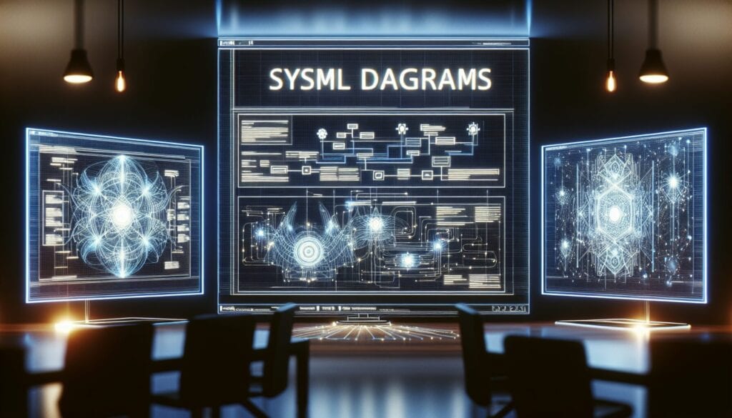
Diagramas SysML
- Metodología ágil, Diseño para la sostenibilidad, Ingeniería de sistemas basada en modelos (MBSE), Mejora de procesos, Gestión de proyectos, Gestión de calidad, Lenguaje de modelado de sistemas (SysML), Lenguaje Unificado de Modelado (UML), Verificación y validación
Objetivo:
Cómo se utiliza:
Ventajas
- Proporciona una forma estandarizada de representar sistemas; facilita la comunicación y la colaboración entre diferentes disciplinas de ingeniería; apoya la ingeniería de sistemas basada en modelos (MBSE); ayuda a gestionar la complejidad.
Contras
- Puede ser complejo de aprender y utilizar eficazmente; requiere herramientas de modelado especializadas; puede percibirse como excesivamente formal para proyectos pequeños; potencial de "hinchazón del lenguaje" debido a su amplitud y a la herencia UML.
Categorías:
- Ingeniería, Diseño de producto, Gestión de proyectos, Gestión de riesgos
Ideal para:
- Modelización y gestión de sistemas complejos y multidisciplinares a lo largo de su ciclo de vida.
SysML diagrams find extensive applications across various industries such as aerospace, automotive, defense, healthcare, and telecommunications, where the design and integration of complex systems are commonplace. During the requirements phase of a project, stakeholders can utilize requirement diagrams to capture and organize user needs, ensuring clarity in what the end product must achieve. The block definition diagram is particularly beneficial in early design stages for representing the system architecture, facilitating discussions among engineers about component interrelations before proceeding to detailed design. Internal block diagrams can then be used in the development phase to illustrate the interactions between components at a deeper level, which can prove invaluable when conducting trade studies and system verification. Parametric diagrams come into play for performance analysis, enabling engineers to evaluate constraints and parameters that define system behavior under various conditions. Typically, a cross-disciplinary team comprising systems engineers, software developers, hardware engineers, and project managers collaborates on these diagrams to ensure that all facets of the design are aligned and that the integration challenges are addressed early on. Utilizing SysML enables model-based systems engineering, which reinforces a holistic view of the project while addressing interdisciplinary requirements, thus enhancing collaboration and reducing the likelihood of costly miscommunications during later stages. The standardization of representations across different teams accelerates the overall workflow, making it easier to share models and documentation through various phases of the system lifecycle, from conceptualization to deployment and maintenance.
Pasos clave de esta metodología
- Define system requirements using requirement diagrams to capture stakeholder needs.
- Create block definition diagrams to represent system elements and their relationships.
- Develop internal block diagrams to illustrate internal system structure and connectivity.
- Construct parametric diagrams to define performance constraints and relationships among system properties.
- Use sequence diagrams to detail interactions and workflows between components.
- Iterate through diagrams as needed to refine and validate system models continuously.
- Integrate and verify models across different engineering disciplines to ensure alignment.
- Conduct reviews and assessments to evaluate system design and functionality against requirements.
Consejos profesionales
- Utilize cross-discipline collaboration sessions to review SysML models, ensuring alignment and addressing discrepancies early in the design phase.
- Leverage the power of parametric diagrams to quantify and validate system performance criteria, providing tangible metrics that guide design decisions.
- Integrate version control tools with your SysML models to track changes over time, facilitating better management of systemic evolution and decision-making processes.
Leer y comparar varias metodologías, recomendamos el
> Amplio repositorio de metodologías <
junto con otras más de 400 metodologías.
Sus comentarios sobre esta metodología o información adicional son bienvenidos en la dirección sección de comentarios ↓ , así como cualquier idea o enlace relacionado con la ingeniería.
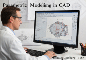
Contexto histórico


1980
1980
1986
1987
1990
1990
1990
1980
1980
1986
1986
1987-03
1990
1990
1992


(si se desconoce la fecha o no es relevante, por ejemplo "mecánica de fluidos", se ofrece una estimación redondeada de su notable aparición)
Publicaciones relacionadas
Gestión de operaciones de fabricación (MOM)
Sistema de Ejecución de Fabricación (MES)
Plan de control de la fabricación
Pruebas manuales
Tablas de evaluación de la manipulación manual (MAC)
ManTRA (Herramienta de evaluación de riesgos en las tareas manuales)